I was looking through all the reference material I could find about this and I am unclear as to what these properties are and where their values come from.
hydro/float-beam-ft
hydro/float-beam-ft2
hydro/float-beam-ft3
hydro/float-beam-ft4
How are they calculated?
I have been tuning the J3Cub floats and have made some great progress as far as I am concerned. They are behaving much better getting up on step and settling. But the changes I had to make are probably a bit unorthodox.
By changing the metrics/hydro-rp-x-in to -100 I am able to get a nice step effect and if very careful able to land without a bunch of bouncing. Even in the 65hp. Although the 65 is definitely underpowered. Is there another, better way to achieve this other than adjusting the rp-x in such an extreme fashion?
Also I am wondering how to change the shape and size of the float surface and its buoyancy. To an extreme! I've looked at and experimented here and there where I thought it might be but still don't have a handle on it. I imagine the hydro/float-beam-ft is part of my puzzle.
Trying to adjust metrics/hydro-length-ft and hydro/hull-length-ft didn't seam to do what I expected.
For example, I am trying to model the tundra tires flotation values, or at least get something similar.
Changing both metrics/hydro-length-ft, hydro/hull-length-ft to a value like .9" didn't seem to let the tail settle on the water like I might expect if there was no longer a long float but only a tire with basically the same beam as the floats.
And the last piece is the flotation values, which ones are they, or are they calculated using a combination of
hydro/float-beam-ft
hydro/float-beam-ft2
hydro/float-beam-ft3
hydro/float-beam-ft4
metrics/hydro-length-ft
metrics/hydro-beam-ft
hydro/hull-length-ft
I also found hydro/drag-tweak-factor extremely useful if I interpolate it with say speed to help adjust the drag after you come off the step but still allow the under power 65 to get to step.
Not so much for hydro/lift-tweak-factor, it didn't seem to do anything noticeable.
Shedding some light on these would likewise be extremely helpful.
Board index ‹ FlightGear ‹ Development ‹ Aircraft
Hydrodynamics hydro/float-beam-ft
26 posts
• Page 1 of 2 • 1, 2
Hydrodynamics hydro/float-beam-ft
![]() by wlbragg » Fri Mar 10, 2017 8:27 pm
by wlbragg » Fri Mar 10, 2017 8:27 pm
Kansas and Ohio/Midwest scenery development.
KEQA, 3AU, KRCP Airport Layout
Intel i7/GeForce RTX 2070/Max-Q
KEQA, 3AU, KRCP Airport Layout
Intel i7/GeForce RTX 2070/Max-Q
-

wlbragg - Posts: 7609
- Joined: Sun Aug 26, 2012 12:31 am
- Location: Kansas (Tornado Alley), USA
- Callsign: WC2020
- Version: next
- OS: Win10/Linux/RTX 2070
Re: Hydrodynamics hydro/float-beam-ft
![]() by AndersG » Fri Mar 10, 2017 9:51 pm
by AndersG » Fri Mar 10, 2017 9:51 pm
wlbragg wrote in Fri Mar 10, 2017 8:27 pm:I was looking through all the reference material I could find about this and I am unclear as to what these properties are and where their values come from.
hydro/float-beam-ft
hydro/float-beam-ft2
hydro/float-beam-ft3
hydro/float-beam-ft4
These are just scaling parameters to redimensionalize the coefficients - just like wing span, cord and wing area are used for aerodynamic coefficients. In this case I probably only used one which is then squared and cubed for those coefficients where length^2 and length^3 is needed to get the right unit of the force or moment.
wlbragg wrote in Fri Mar 10, 2017 8:27 pm:How are they calculated?
The beam is just the beam (I guess typically at the step) of a single float in ft, beam squared, cubed and so on is just that number cubed, squared and so on.
The crucial part is, of course, that the coefficient (if it came from any sort of real data...) was made dimensionless with the same measure.
wlbragg wrote in Fri Mar 10, 2017 8:27 pm:I have been tuning the J3Cub floats and have made some great progress as far as I am concerned. They are behaving much better getting up on step and settling. But the changes I had to make are probably a bit unorthodox.
By changing the metrics/hydro-rp-x-in to -100 I am able to get a nice step effect and if very careful able to land without a bunch of bouncing. Even in the 65hp. Although the 65 is definitely underpowered. Is there another, better way to achieve this other than adjusting the rp-x in such an extreme fashion?
Also I am wondering how to change the shape and size of the float surface and its buoyancy. To an extreme! I've looked at and experimented here and there where I thought it might be but still don't have a handle on it. I imagine the hydro/float-beam-ft is part of my puzzle.
That's pretty unorthodox as it has left even the tiniest connection with the physics of the real system, more or less... :)
The size and shape of the float in terms of buoyancy is expressed in the tables (buoyancy and the moments due to buoyancy). These tables need to be changed (read: recomputed) to reflect the actual shape of the float in question.
wlbragg wrote in Fri Mar 10, 2017 8:27 pm:Trying to adjust metrics/hydro-length-ft and hydro/hull-length-ft didn't seam to do what I expected.
For example, I am trying to model the tundra tires flotation values, or at least get something similar.
Changing both metrics/hydro-length-ft, hydro/hull-length-ft to a value like .9" didn't seem to let the tail settle on the water like I might expect if there was no longer a long float but only a tire with basically the same beam as the floats.
And the last piece is the flotation values, which ones are they, or are they calculated using a combination of
hydro/float-beam-ft
hydro/float-beam-ft2
hydro/float-beam-ft3
hydro/float-beam-ft4
metrics/hydro-length-ft
metrics/hydro-beam-ft
hydro/hull-length-ft
The coefficients are dimensionless and are redimensionalized using float-beam-ft and so on (it should be obvious which is used when looking in the file).
Due to the in-development state of the hydrodynamics system there are a bit too many different dimensions in use there but by searching in the file you should be able to figure out where they are used. The ones in metrics/ and hydro/hull-length-ft are used in the generic hydrodynamics system for computing wave interactions.
IIRC, the aircraft specific hydrodynamics file uses only float-beam-ft (and its powers) to redimensionalize the coefficients there.
The shape of your tundra tires is quite far from the shape of the floats so you need new coefficient tables.
wlbragg wrote in Fri Mar 10, 2017 8:27 pm:I also found hydro/drag-tweak-factor extremely useful if I interpolate it with say speed to help adjust the drag after you come off the step but still allow the under power 65 to get to step.
Not so much for hydro/lift-tweak-factor, it didn't seem to do anything noticeable.
Shedding some light on these would likewise be extremely helpful.
They are just multipliers for the respective function. Now, I think you use the unphysical planing model that we used on the c172p - which is just reusing the hydrostatic tables but multiplied by the dynamic pressure so I think there is no nice interpretation, unfortunately.
Using the hydrodynamic-planing/hydrodynamic-planing-floats system takes the planing part closer to the real physics but has other drawbacks.
Callsign: SE-AG
Aircraft (uhm...): Submarine Scout, Zeppelin NT, ZF Navy free balloon, Nordstern, Hindenburg, Short Empire flying-boat, ZNP-K, North Sea class, MTB T21 class, U.S.S. Monitor, MFI-9B, Type UB I submarine, Gokstad ship, Renault FT.
Aircraft (uhm...): Submarine Scout, Zeppelin NT, ZF Navy free balloon, Nordstern, Hindenburg, Short Empire flying-boat, ZNP-K, North Sea class, MTB T21 class, U.S.S. Monitor, MFI-9B, Type UB I submarine, Gokstad ship, Renault FT.
- AndersG
- Posts: 2527
- Joined: Wed Nov 29, 2006 10:20 am
- Location: Göteborg, Sweden
- Callsign: SE-AG
- OS: Debian GNU Linux
Re: Hydrodynamics hydro/float-beam-ft
![]() by wlbragg » Fri Mar 10, 2017 10:44 pm
by wlbragg » Fri Mar 10, 2017 10:44 pm
Thank you Anders, that filled in the gaps nicely. Now I have an idea as to where to go from here.
I wondered what those were for and why we weren't using them in the two craft. Good to know.
Yeah, I knew it had to be wrong but it really smoothed things out. I actually could get by at 0, it was a big improvement but the farther I went the better if felt. I will revisit it now that I have more of the puzzle. Maybe I can get it back to a reasonable number.
This is really fun stuff when you start to see things acting like you expect them to. It is a joy to land and take off when it behaves as it should. Getting up on the step is so cool! I read about pilot actions with the yoke on takeoff, like push forward at first, it actually behaves like advertised by experienced pilots.
My ultimate goal is to get the tundra tires to plane and reenact the world record ski run done on Lake Tahoe. I have it working now somewhat, but cheating.
Thanks again.
Using the hydrodynamic-planing/hydrodynamic-planing-floats system takes the planing part closer to the real physics but has other drawbacks.
I wondered what those were for and why we weren't using them in the two craft. Good to know.
That's pretty unorthodox as it has left even the tiniest connection with the physics of the real system, more or less...
Yeah, I knew it had to be wrong but it really smoothed things out. I actually could get by at 0, it was a big improvement but the farther I went the better if felt. I will revisit it now that I have more of the puzzle. Maybe I can get it back to a reasonable number.
This is really fun stuff when you start to see things acting like you expect them to. It is a joy to land and take off when it behaves as it should. Getting up on the step is so cool! I read about pilot actions with the yoke on takeoff, like push forward at first, it actually behaves like advertised by experienced pilots.
My ultimate goal is to get the tundra tires to plane and reenact the world record ski run done on Lake Tahoe. I have it working now somewhat, but cheating.
Thanks again.
Kansas and Ohio/Midwest scenery development.
KEQA, 3AU, KRCP Airport Layout
Intel i7/GeForce RTX 2070/Max-Q
KEQA, 3AU, KRCP Airport Layout
Intel i7/GeForce RTX 2070/Max-Q
-
wlbragg - Posts: 7609
- Joined: Sun Aug 26, 2012 12:31 am
- Location: Kansas (Tornado Alley), USA
- Callsign: WC2020
- Version: next
- OS: Win10/Linux/RTX 2070
Re: Hydrodynamics hydro/float-beam-ft
![]() by AndersG » Fri Mar 10, 2017 11:00 pm
by AndersG » Fri Mar 10, 2017 11:00 pm
wlbragg wrote in Fri Mar 10, 2017 10:44 pm:Thank you Anders, that filled in the gaps nicely. Now I have an idea as to where to go from here.Using the hydrodynamic-planing/hydrodynamic-planing-floats system takes the planing part closer to the real physics but has other drawbacks.
I wondered what those were for and why we weren't using them in the two craft. Good to know.
IIRC we have discussed the use or not of these before? The main drawback that I'm aware of is the higher FDM rate required that increases the CPU use by JSBSim significantly which, on some systems, significantly reduces the frame rate in FG. On my system this is not the bottleneck restricting FG frame rate, though.
IIRC the J3 Cub hydrodynamics is based on the c172p file? I think there may be a middle way that makes it easier to support the different variants of your aircraft: if you start from the MFI-9B hydrodynamics but strip out the hydrodynamic-planing-floats system and functions and replace them by planing functions based on those in the c172p (you'll need separate functions for the left and right float, though). The MFI-9B hydrodynamics is based around hydrostatic coefficients for a single float while the coefficients in the c172p one is for both floats combined. Making hydrostatic coefficients for a single tire shouldn't be that hard - I think you can compute reasonable ones directly using the geometry without resorting to Gerris.
I hope you have found my wiki HowTo, although it is very unfinished:
http://wiki.flightgear.org/Howto:Modelling_hydrodynamics_in_JSBSim
Callsign: SE-AG
Aircraft (uhm...): Submarine Scout, Zeppelin NT, ZF Navy free balloon, Nordstern, Hindenburg, Short Empire flying-boat, ZNP-K, North Sea class, MTB T21 class, U.S.S. Monitor, MFI-9B, Type UB I submarine, Gokstad ship, Renault FT.
Aircraft (uhm...): Submarine Scout, Zeppelin NT, ZF Navy free balloon, Nordstern, Hindenburg, Short Empire flying-boat, ZNP-K, North Sea class, MTB T21 class, U.S.S. Monitor, MFI-9B, Type UB I submarine, Gokstad ship, Renault FT.
- AndersG
- Posts: 2527
- Joined: Wed Nov 29, 2006 10:20 am
- Location: Göteborg, Sweden
- Callsign: SE-AG
- OS: Debian GNU Linux
Re: Hydrodynamics hydro/float-beam-ft
![]() by wlbragg » Fri Mar 10, 2017 11:16 pm
by wlbragg » Fri Mar 10, 2017 11:16 pm
IIRC the J3 Cub hydrodynamics is based on the c172p file?
Yes it is.
I hope you have found my wiki HowTo, although it is very unfinished:
Yeah I did and it was really helpful with the stuff it covered. Just too much not covered yet. But I totally understand that, making documentation is about as boring as it gets.
Kansas and Ohio/Midwest scenery development.
KEQA, 3AU, KRCP Airport Layout
Intel i7/GeForce RTX 2070/Max-Q
KEQA, 3AU, KRCP Airport Layout
Intel i7/GeForce RTX 2070/Max-Q
-
wlbragg - Posts: 7609
- Joined: Sun Aug 26, 2012 12:31 am
- Location: Kansas (Tornado Alley), USA
- Callsign: WC2020
- Version: next
- OS: Win10/Linux/RTX 2070
Re: Hydrodynamics hydro/float-beam-ft
![]() by AndersG » Fri Mar 10, 2017 11:33 pm
by AndersG » Fri Mar 10, 2017 11:33 pm
It might also be worth noting that the hydrostatic coefficients might not be undimensional at all - at least I've written something along those lines in my summarize_experiment.sh file. Proceed with care and double-check the units... [EDIT]Indeed, the forces and moments are not dimensionless - the length/area/volume scale is part of the "coefficients" - only fluid density and local gravity is extracted from them.[/EDIT]
Callsign: SE-AG
Aircraft (uhm...): Submarine Scout, Zeppelin NT, ZF Navy free balloon, Nordstern, Hindenburg, Short Empire flying-boat, ZNP-K, North Sea class, MTB T21 class, U.S.S. Monitor, MFI-9B, Type UB I submarine, Gokstad ship, Renault FT.
Aircraft (uhm...): Submarine Scout, Zeppelin NT, ZF Navy free balloon, Nordstern, Hindenburg, Short Empire flying-boat, ZNP-K, North Sea class, MTB T21 class, U.S.S. Monitor, MFI-9B, Type UB I submarine, Gokstad ship, Renault FT.
- AndersG
- Posts: 2527
- Joined: Wed Nov 29, 2006 10:20 am
- Location: Göteborg, Sweden
- Callsign: SE-AG
- OS: Debian GNU Linux
Re: Hydrodynamics hydro/float-beam-ft
![]() by wlbragg » Sat Mar 11, 2017 7:17 pm
by wlbragg » Sat Mar 11, 2017 7:17 pm
In this case I probably only used one which is then squared and cubed for those coefficients where length^2 and length^3 is needed to get the right unit of the force or moment.
Why do you think you might have used two different ones?
hydro/float-beam-ft2 = 7.34 or .187m in "Drag due to displacement of float" and "Side force due to floats. Guessed".
hydro/float-beam-ft3 = 19.9 or .505m in "Yaw moment due to float (per radian beta)" and "Hydrodynamic yaw moment due to rudder".
And do these numbers represent these position on the X or something else? I can't find any correlation to representing anything on the Y.

Kansas and Ohio/Midwest scenery development.
KEQA, 3AU, KRCP Airport Layout
Intel i7/GeForce RTX 2070/Max-Q
KEQA, 3AU, KRCP Airport Layout
Intel i7/GeForce RTX 2070/Max-Q
-
wlbragg - Posts: 7609
- Joined: Sun Aug 26, 2012 12:31 am
- Location: Kansas (Tornado Alley), USA
- Callsign: WC2020
- Version: next
- OS: Win10/Linux/RTX 2070
Re: Hydrodynamics hydro/float-beam-ft
![]() by AndersG » Sat Mar 11, 2017 9:16 pm
by AndersG » Sat Mar 11, 2017 9:16 pm
Nonono, hydro/float-beam-ft2 is hydro/float-beam-ft*hydro/float-beam-ft and hydro/float-beam-ft3 is hydro/float-beam-ft*hydro/float-beam-ft*hydro/float-beam-ft.
I borrowed the idea of using a single measure as the basis for reference length, area and volume from the aerodynamics of airships where it is common to use the envelope volume as the reference volume, the volume^2/3 as the reference area and the volume^1/3 as the reference length.
The reason different functions use different references is that the forces need an area while the moments need a volume for the units to work out. Compare with ordinary aerodynamics functions in JSBSim.
Last edited by Johan G on Sun Mar 12, 2017 8:05 am, edited 1 time in total.
Reason: No need to quote the entire preceeding post
Reason: No need to quote the entire preceeding post
Callsign: SE-AG
Aircraft (uhm...): Submarine Scout, Zeppelin NT, ZF Navy free balloon, Nordstern, Hindenburg, Short Empire flying-boat, ZNP-K, North Sea class, MTB T21 class, U.S.S. Monitor, MFI-9B, Type UB I submarine, Gokstad ship, Renault FT.
Aircraft (uhm...): Submarine Scout, Zeppelin NT, ZF Navy free balloon, Nordstern, Hindenburg, Short Empire flying-boat, ZNP-K, North Sea class, MTB T21 class, U.S.S. Monitor, MFI-9B, Type UB I submarine, Gokstad ship, Renault FT.
- AndersG
- Posts: 2527
- Joined: Wed Nov 29, 2006 10:20 am
- Location: Göteborg, Sweden
- Callsign: SE-AG
- OS: Debian GNU Linux
Re: Hydrodynamics hydro/float-beam-ft
![]() by wlbragg » Sat Mar 11, 2017 9:22 pm
by wlbragg » Sat Mar 11, 2017 9:22 pm
Oh, OK, gees, it's like talking to a two year old, yeah? Sorry, I am not knowledgeable on any of this stuff. You said it previously, "squared and cubed for those coefficients where length^2 and length^3 is needed to get the right unit of the force or moment." It simply didn't sink in!
Kansas and Ohio/Midwest scenery development.
KEQA, 3AU, KRCP Airport Layout
Intel i7/GeForce RTX 2070/Max-Q
KEQA, 3AU, KRCP Airport Layout
Intel i7/GeForce RTX 2070/Max-Q
-
wlbragg - Posts: 7609
- Joined: Sun Aug 26, 2012 12:31 am
- Location: Kansas (Tornado Alley), USA
- Callsign: WC2020
- Version: next
- OS: Win10/Linux/RTX 2070
Re: Hydrodynamics hydro/float-beam-ft
![]() by AndersG » Sat Mar 11, 2017 10:13 pm
by AndersG » Sat Mar 11, 2017 10:13 pm
No problem.
This image might help a bit when/if looking at the MFI-9B hydrodynamics:
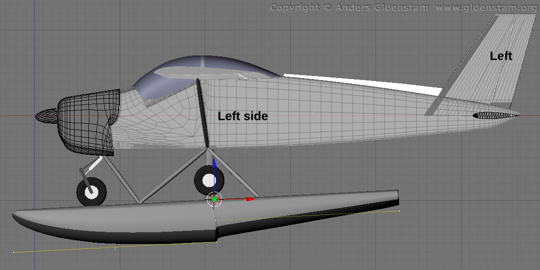
The main hydrodynamic reference point, HYDRO RP, is where the marker is. Each float has its own hydrodynamic reference point that is in the same X and Z position but displaced sidewise to the center line of the respective float. The 0 pitch reference line for the hydrodynamics system is offset by -3 deg compared to that of the model and the aerodynamic system.
The yellow marked object shows the position of the planing surfaces that has been entered into the hydrodynamic-planing-floats system. As this system can only deal with flat planing surfaces there is a rather large discrepancy but it is not that noticeable at runtime.
This image might help a bit when/if looking at the MFI-9B hydrodynamics:
The main hydrodynamic reference point, HYDRO RP, is where the marker is. Each float has its own hydrodynamic reference point that is in the same X and Z position but displaced sidewise to the center line of the respective float. The 0 pitch reference line for the hydrodynamics system is offset by -3 deg compared to that of the model and the aerodynamic system.
The yellow marked object shows the position of the planing surfaces that has been entered into the hydrodynamic-planing-floats system. As this system can only deal with flat planing surfaces there is a rather large discrepancy but it is not that noticeable at runtime.
Callsign: SE-AG
Aircraft (uhm...): Submarine Scout, Zeppelin NT, ZF Navy free balloon, Nordstern, Hindenburg, Short Empire flying-boat, ZNP-K, North Sea class, MTB T21 class, U.S.S. Monitor, MFI-9B, Type UB I submarine, Gokstad ship, Renault FT.
Aircraft (uhm...): Submarine Scout, Zeppelin NT, ZF Navy free balloon, Nordstern, Hindenburg, Short Empire flying-boat, ZNP-K, North Sea class, MTB T21 class, U.S.S. Monitor, MFI-9B, Type UB I submarine, Gokstad ship, Renault FT.
- AndersG
- Posts: 2527
- Joined: Wed Nov 29, 2006 10:20 am
- Location: Göteborg, Sweden
- Callsign: SE-AG
- OS: Debian GNU Linux
Re: Hydrodynamics hydro/float-beam-ft
![]() by Alant » Sun Mar 12, 2017 1:14 am
by Alant » Sun Mar 12, 2017 1:14 am
This topic brings back some ancient memories for me.
Back in the 1960´s I was given an undergraduate project to simulate Donald Campbell´s Bluebird speedboat. I still have a folder with my notes and data.
http://www.bbc.com/news/uk-england-cumbria-38496708
"One day" I hope to revive this project. The equipment I was given was a dozen or so operational amplifiers (to build an analogue computer) and a multichannel oscilloscope ( to record the response).
I was a student in the aero department at Imperial College where the wind tunnel work was done for Bluebird.
My own theory is that on the return run he hit the waves from the first run, which had the same wavelength (and as he was travelling at a similar speed would be of the same frequency) which could excite a lightly damped lateral oscillation. The machine was aerodynamically unstable in pitch and above about 5 degrees of incidence would become airborne with disastrous consequences..
Alan
- Alant
- Posts: 1223
- Joined: Wed Jun 23, 2010 6:58 am
- Location: Portugal
- Callsign: Tarnish99
- Version: latest Git
- OS: Windows 10/11
Re: Hydrodynamics hydro/float-beam-ft
![]() by wlbragg » Sun Mar 12, 2017 7:14 am
by wlbragg » Sun Mar 12, 2017 7:14 am
AndersG wrote in Sat Mar 11, 2017 10:13 pm:This image might help a bit when/if looking at the MFI-9B hydrodynamics:
I can't get to the image. All I see is the word "image". If I try to open the url for it or copy it I get nothing.
Trying to get to http://www.gidenstam.org just gives me "Waiting for http://www.gidenstam.org"
I'll keep trying tomorrow, I really want to see this image.
Kansas and Ohio/Midwest scenery development.
KEQA, 3AU, KRCP Airport Layout
Intel i7/GeForce RTX 2070/Max-Q
KEQA, 3AU, KRCP Airport Layout
Intel i7/GeForce RTX 2070/Max-Q
-
wlbragg - Posts: 7609
- Joined: Sun Aug 26, 2012 12:31 am
- Location: Kansas (Tornado Alley), USA
- Callsign: WC2020
- Version: next
- OS: Win10/Linux/RTX 2070
Re: Hydrodynamics hydro/float-beam-ft
![]() by AndersG » Sun Mar 12, 2017 9:34 am
by AndersG » Sun Mar 12, 2017 9:34 am
Sorry, there seems to have been a situation with my network connection last night. It seems ok again now.
Callsign: SE-AG
Aircraft (uhm...): Submarine Scout, Zeppelin NT, ZF Navy free balloon, Nordstern, Hindenburg, Short Empire flying-boat, ZNP-K, North Sea class, MTB T21 class, U.S.S. Monitor, MFI-9B, Type UB I submarine, Gokstad ship, Renault FT.
Aircraft (uhm...): Submarine Scout, Zeppelin NT, ZF Navy free balloon, Nordstern, Hindenburg, Short Empire flying-boat, ZNP-K, North Sea class, MTB T21 class, U.S.S. Monitor, MFI-9B, Type UB I submarine, Gokstad ship, Renault FT.
- AndersG
- Posts: 2527
- Joined: Wed Nov 29, 2006 10:20 am
- Location: Göteborg, Sweden
- Callsign: SE-AG
- OS: Debian GNU Linux
Re: Hydrodynamics hydro/float-beam-ft
![]() by wlbragg » Sun Mar 12, 2017 9:57 am
by wlbragg » Sun Mar 12, 2017 9:57 am
Yep, got it, thanks!
Kansas and Ohio/Midwest scenery development.
KEQA, 3AU, KRCP Airport Layout
Intel i7/GeForce RTX 2070/Max-Q
KEQA, 3AU, KRCP Airport Layout
Intel i7/GeForce RTX 2070/Max-Q
-
wlbragg - Posts: 7609
- Joined: Sun Aug 26, 2012 12:31 am
- Location: Kansas (Tornado Alley), USA
- Callsign: WC2020
- Version: next
- OS: Win10/Linux/RTX 2070
Re: Hydrodynamics hydro/float-beam-ft
![]() by wlbragg » Wed Mar 15, 2017 2:50 am
by wlbragg » Wed Mar 15, 2017 2:50 am
Why are there the amount of tables used for hydro/float/height-agl-ft?
What are the relationships, as in, height-agl-ft = 4 or 5 or 6?
Why does it start at 4 and end at 8?
Is any of this documented anywhere? If so I apologize for not doing the legwork to find it.
Also, could you explain what this means, what offset are you referring to?
What are the relationships, as in, height-agl-ft = 4 or 5 or 6?
Why does it start at 4 and end at 8?
Is any of this documented anywhere? If so I apologize for not doing the legwork to find it.
- Code: Select all
<table>
   <independentVar lookup="row">hydro/float/pitch-deg</independentVar>
   <independentVar lookup="column">hydro/float/roll-deg</independentVar>
   <independentVar lookup="table">hydro/float/height-agl-ft</independentVar>
      <tableData breakPoint="4.0">
        ~~~~~~~~~
        ~~~~~~~~~
      </tableData>
      <tableData breakPoint="5.0">
        ~~~~~~~~~
        ~~~~~~~~~
      </tableData>
      <tableData breakPoint="6.0">
        ~~~~~~~~~
        ~~~~~~~~~
      </tableData>
      <tableData breakPoint="7.0">
        ~~~~~~~~~
        ~~~~~~~~~
      </tableData>
      <tableData breakPoint="8.0">

      </tableData>
Also, could you explain what this means, what offset are you referring to?
- Code: Select all
<fcs_function name="hydro/float/height-agl-ft">
  <description>
    The float height with waves and squat due to the transverse wave applied.
  </description>
    <function>
       <sum>
          <property>hydro/height-agl-ft</property>
            <!-- Account for the 6.5cm vertical offset of the float model. -->
             <value>-0.2133</value>
Kansas and Ohio/Midwest scenery development.
KEQA, 3AU, KRCP Airport Layout
Intel i7/GeForce RTX 2070/Max-Q
KEQA, 3AU, KRCP Airport Layout
Intel i7/GeForce RTX 2070/Max-Q
-
wlbragg - Posts: 7609
- Joined: Sun Aug 26, 2012 12:31 am
- Location: Kansas (Tornado Alley), USA
- Callsign: WC2020
- Version: next
- OS: Win10/Linux/RTX 2070
26 posts
• Page 1 of 2 • 1, 2
Who is online
Users browsing this forum: No registered users and 11 guests