The guidance is based on the real closed loop used in the Shuttle, known as Power Explicit Guidance https://www.orbiterwiki.org/wiki/Powered_Explicit_Guidance.
Documentations
*A very detailled and complete topic about the guidance by Noiredd who implemented it in Matlab and KSP: https://github.com/Noiredd/PEGAS-MATLAB ... cs/upfg.md
*A deeper document with nice schematic drawings: Ascent Guidance Navigation and Control Shuttle Workbook (page 111) https://www.google.com/search?client=firefox-b-d&q=ascent+guidance+workbook+shuttle
*Original formulation of the Unified Power Explicit Guidance with equations and algorithms: ntrs.nasa.gov/citations/19740004402
*A paper about enhancements made over the years to the original ascent guidance: ntrs.nasa.gov/citations/20180002035
Overview
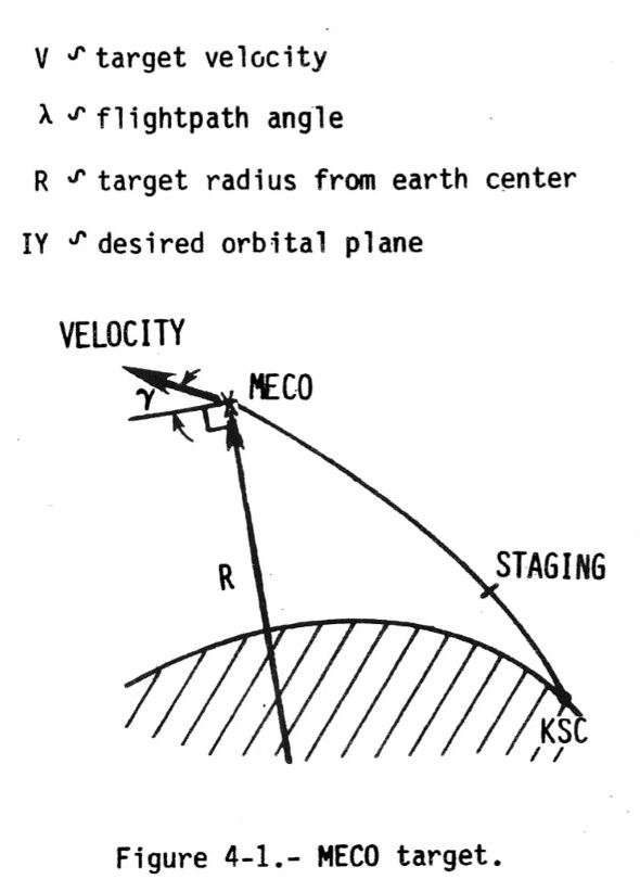
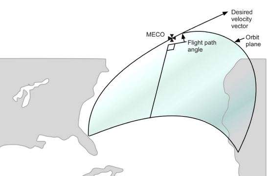
Second stage guidance functions very differently from first stage guidance in that second stage guidance is closed loop. Second stage guidance computes the control variables (essentially commanded attitude and attitude rates) and burn time to go (TGO) in such a way that the vehicle flies from the current state to the prescribed target conditions (altitude, velocity, flight path angle, and orbit plane) within trajectory constraints. It solves this two point boundary value problem each cycle (every 1.92 seconds). One limitation of second stage guidance is that it doesn't calculate if there is enough propellant to reach the desired MECO conditions.
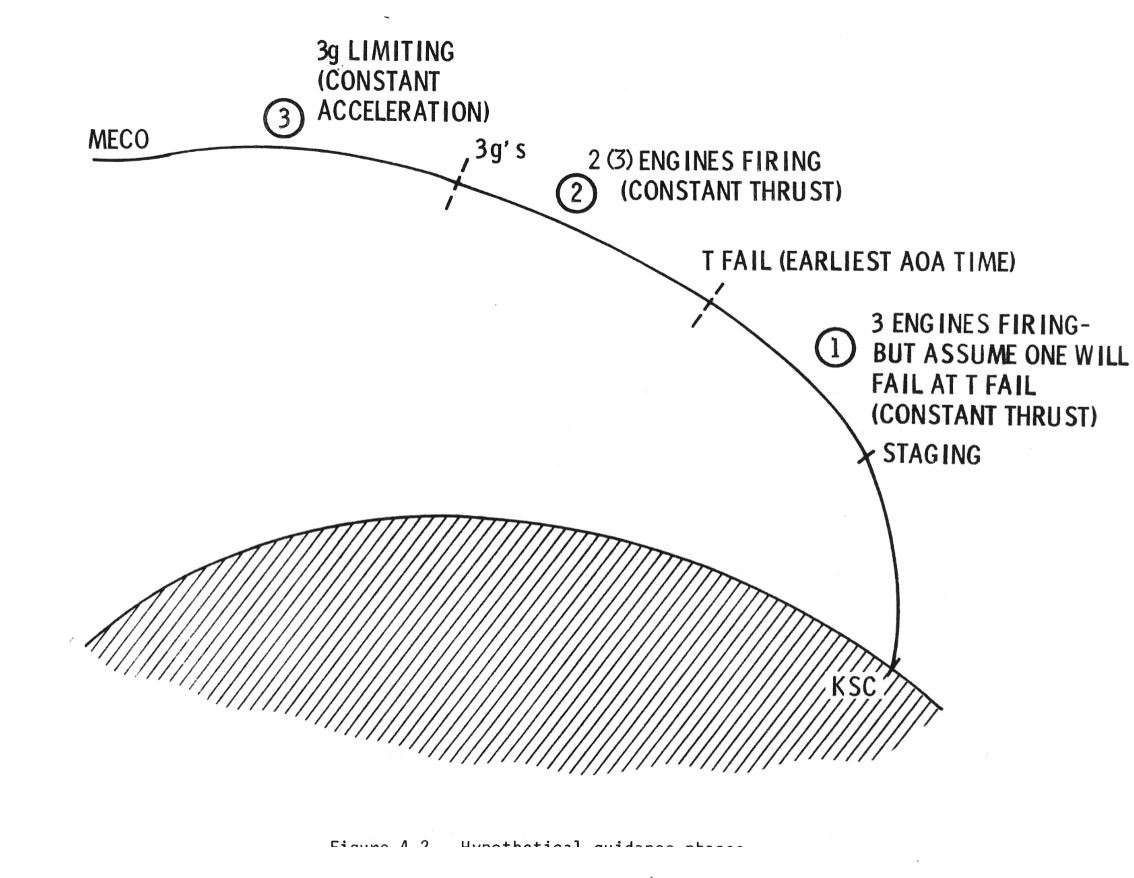
The powered explicit guidance (PEG) scheme used by second stage guidance nominally operates in two phases. The first phase computes throttle and attitude commands based on three SSMEs and a constant thrust requirement until an acceleration of 3g is reached. At that time, the second phase, which uses variable throttle to maintain a constant acceleration, is entered. If an engine failure is detected, a third phase of PEG, which computes the necessary guidance commands using constant thrust to aim for the desired targets using two SSMEs, is entered (assuming no RTLS or TAL abort).
During current shuttle operations, only two phases of PEG are used, constant thrust through 3g and then variable thrust through main engine cutoff (MECO). STS-1 and STS-26, in order to prevent or reduce abort gaps, flew higher than normal trajectories, called lofted or abort shaped. This method required the third PEG phase, which ran from SRB sep to T_FAIL (I-loaded MET) and achieved lofting by assuming that an engine would fail causing loss of performance at the time T_FAIL. When T_FAIL occurred, PEG stopped assuming that an engine would fail. A drawback with this method was discovered later, however. The lofted trajectories caused “black zones,” or regions where an unsurvivable entry/pullout condition would be created if two engines actually did fail (CA). For this reason and the fact that abort shaping costs thousands of pounds of nominal ascent performance (payload), the I-load, T_FAIL is now set to zero, and lofted trajectories are not currently planned.
Second stage guidance performs yaw steering to achieve the desired orbit plane. The desired orbit plane is defined by the unitized negative angular momentum vector (I-loads), commonly referred to as the IY vector. The x and y components of the IY vector define the nodal crossing, while the z component defines the inclination. For missions which do not involve rendezvous with a vehicle already in orbit (referred to as the “target”), the IYs are defined during the flight design process approximately 6 months prior to launch. These missions employ “earth fixed” yaw steering since the trajectory relative to the earth remains the same regardless of launch time. In order to successfully launch into orbit and rendezvous with another vehicle already in space, the orbiter must end up in the same orbital plane and altitude as the other vehicle.
Forty seconds prior to MECO, guidance no longer seeks to achieve the altitude and orbital plane position targets. Common terminology is, “at MECO minus 40 seconds, the position constraints are released.” Without this constraint release, when TGO becomes small, a small change in position error would produce large changes in the thrust turning rate vector and over controlling would result. Note also that the cutoff time (TGO) calculation includes the predicted velocity change from the time minimum throttle is commanded to burnout. This corresponds to the predicted tailoff impulse from each active SSME and is known as fine count. Fine count occurs 10 seconds prior to MECO for nominal ascent, ATO, and TAL and 6 seconds prior to powered pitchdown for RTLS. It is at fine count where second stage, closed loop guidance is terminated and the SSMEs are commanded to a lower power level, usually 67% for three engines running or 91% for one or two engines running (note that the SSMEs aren't throttled back until powered pitchdown during an RTLS). Thereafter, the flight path angle constraint is released, such that TGO is computed solely on the desired velocity change (VGO). When guidance sees the shuttle at the correct inertial velocity (VI), all SSMEs are commanded to shut down.
How does it look like in FG ?
It is almost transparent for the user.
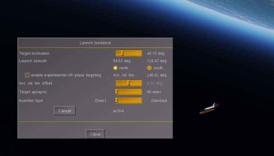
The layout canvas to choose the Apogee and Orbital plane targets is always the same.
One addition, the choice between a Standard and Direct Insertion.
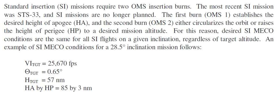
*A Standard Insertion (SI) mission requires two OMS insertion burns to raise the Perigee and circularize the Orbit. Those missions were no longer planned after STS-33.
SI will be automatically used if the Apogee requested is below 100 Nm.
The MECO altitude is around 360000 feet and forecasted Perigee around 10 Nm.
The earlysts.xml config file is a good example of Standard Insertion mission (Apogee at 80 Nm)
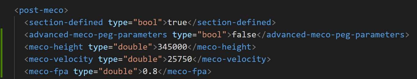
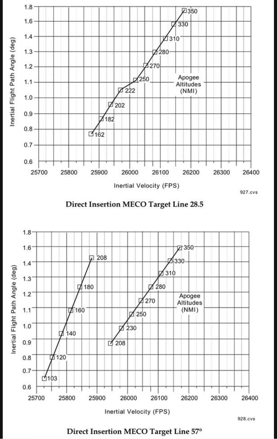
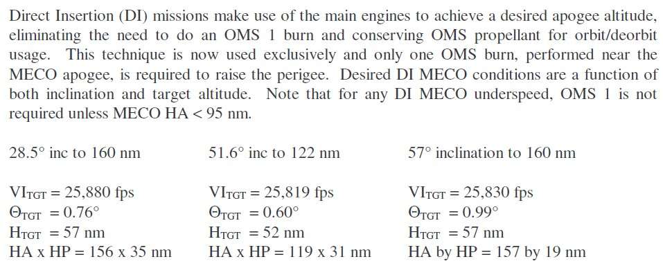
*A Direct Insertion (DI) mission makes use of the main engines to achieve a higher desired apogee altitude, eliminating the need to do an OMS1 burn and conserving OMS propellant for orbit/deorbit usage.
DI will be automatically used if the Apogee requested is above 100 Nm.
The MECO altitude is around 345000 feet and forecasted Perigee around 30 Nm.
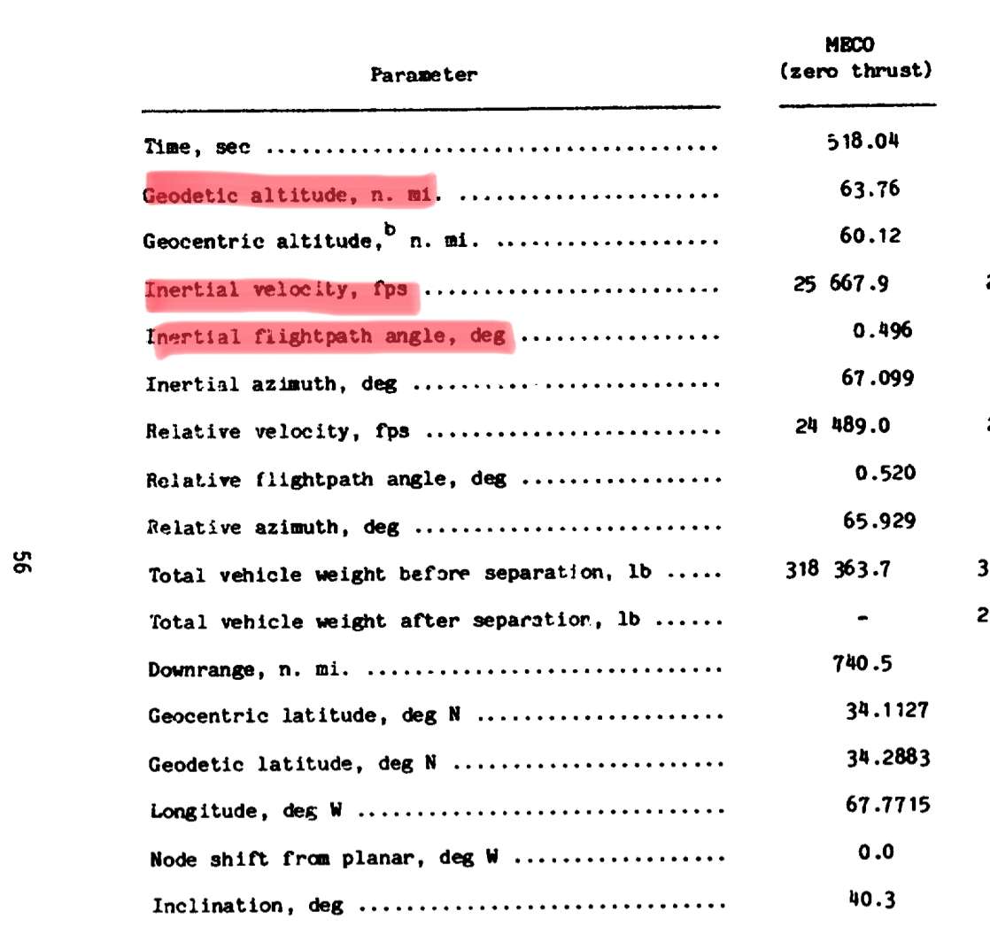
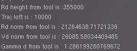
Once everything is set up, those targets will be converted into PEG MECO targets (MECO Altitude, Velocity, Flight Path Angle, Orbital plane vector).
In a future commit, it will be possible for advanced users (who might want to use directly real values from SCOM part 9 - MECO targets) to set up those PEG MECO targets directly into the mission file.
The mission config file options concerning Stage1 (srb climbout) / Stage2 (ballistic climb angle) and trajectory loft are untouched.
Ballistic climb angle will affect the MECO Inertial Flight Path targeted and Traj Loft the Alitutde at MECO.
It is better to play with it carefully as it might break the guidance if set unproperly
- Code: Select all
<srb-climbout-ang-bias-deg type="double">0.0</srb-climbout-ang-bias-deg>
<ballistic-climb-ang-bias-deg type="double">0.0</ballistic-climb-ang-bias-deg>
<trajectory-loft-ft type="double">10000.0</trajectory-loft-ft>
The harmful one is the trajectory loft. The bad side a highly lofted trajectory is the harder entry G wise in case of several engine failures and Contigency ops (More Black Zone where the Shuttle will probably exceed max G loads).
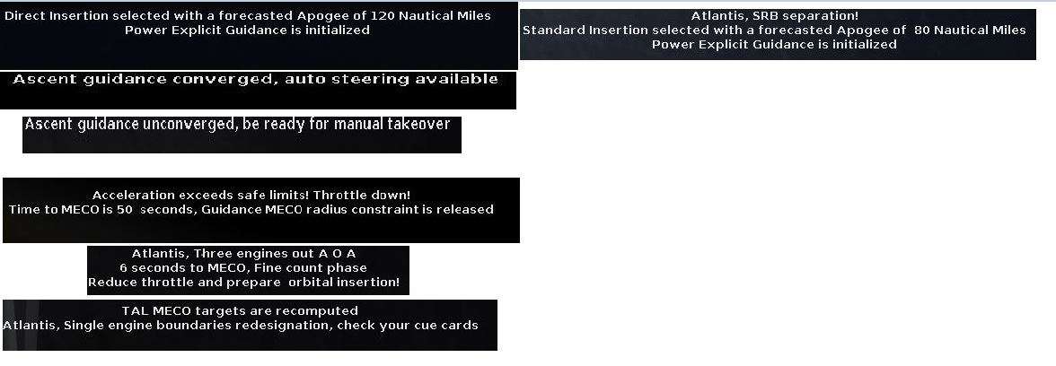
Some new help messages are available.
*PEG initialization at SRB sep
*Guidance convergence state (Auto steering or CSS required)
*Constraints released on some MECO targets close to engines cutoff (around 40 seconds before MECO)
*PEG exited close to MECO (6 to 15 seconds before it), fine count.
*TAL MECO targets recomputation
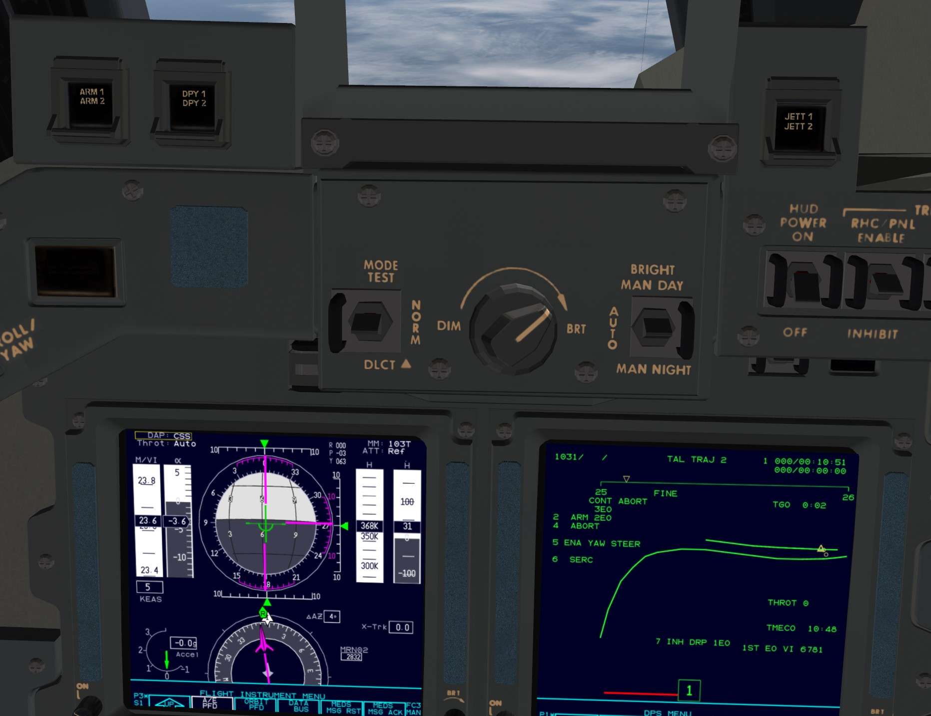
Some slight changes on the PFD.
If guidance is unconverged, Attitude error needles are stowed (left) and vice-versa (right)
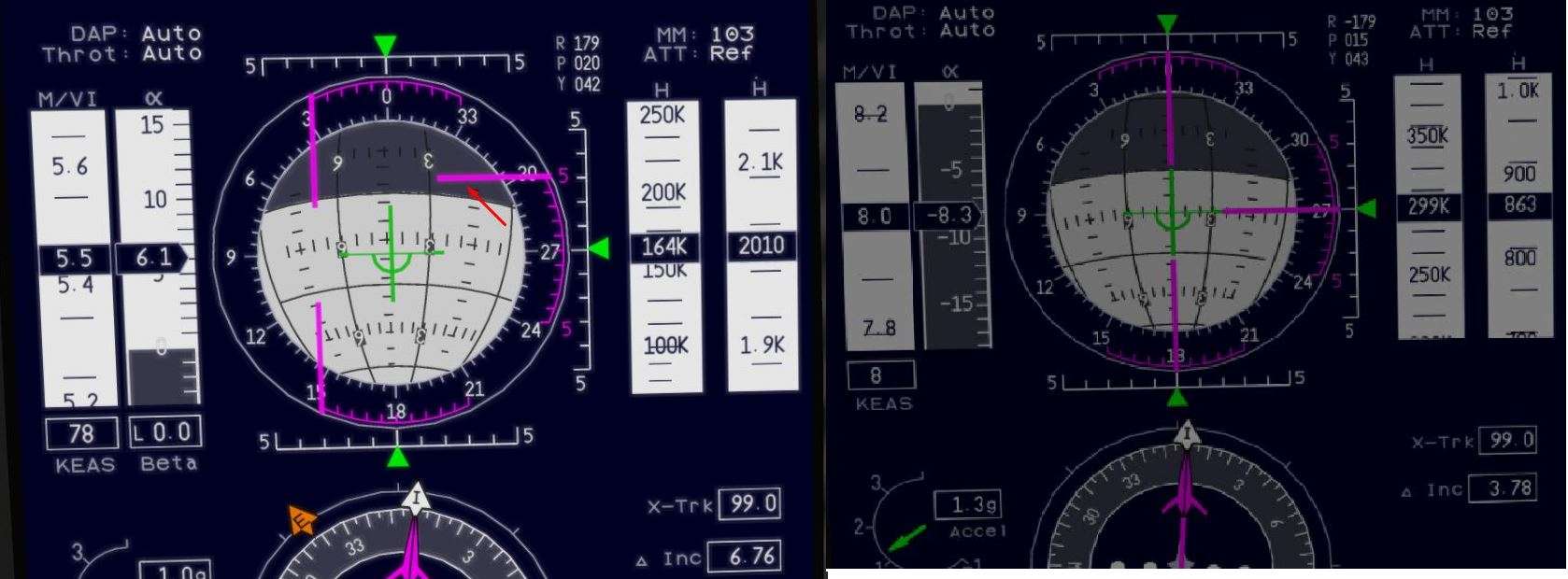
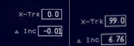
Lateral crosstrack deviation from the targeted Orbital plane in Nm (X - Trk)
Concerning ATO or engine failures withtout aborts (Press to MECO and Single Engine Press to MECO), the algorithm will take into account the decrease in thrust and adjust the steering.
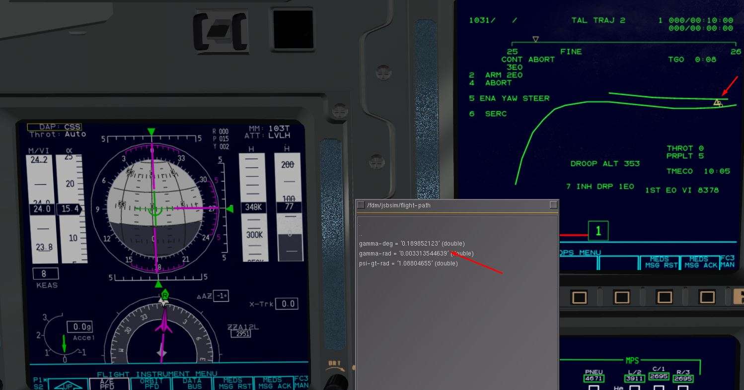
Concerning TAL, the MECO targets will be recomputed (shallower flight path, current orbital plane targeted, higher MECO altitude)
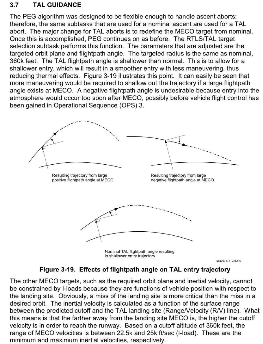
An example there, Shallow Flight path (0.20° ish) and a slightly higher MECO altitude that a Direct Insertion one (Upper Green Line) // 350000 feet for now.
After a Droop, PEG guidance will probably be in an unconverged state and a TAL abort would be required.
TAL targets after a droop are the same than for a normal TAL. The MECO altitude is changed and lowered to 330000 feet to avoid unnecessary propellant waste.
Guidance may stay unconverged for a while and manual steering will be mandatory until guidance is reconverged (help message will annunciate that).
The aim there is to have a shallow flight path to do a Nominal OPS 3 entry with a probable bailout.