Board index FlightGear Media

Space Shuttle Tutorial Full Entry: From Heaven to Ground

Screenshots, videos, sound recording etc. taken in/with FlightGear.

Space Shuttle Tutorial Full Entry: From Heaven to Ground

Postby GinGin » Sun Oct 29, 2017 9:07 pm

Hello everybody,


You will find here a tutorial concerning all the Entry preparation, followed by deorbit burn, entry, TAEM and Landing in KSC.
It's pretty heavy on screen ( around 100), I can split it up or convert it to PDF it is too long to load.

Wiki will be updated also


Nominaly, Pre Deorbit Preparation begins 4 h before deorbit burn, 4h45 before landing at KSC. Long preparation to allow sufficient time to the Freon stocked in Radiators to be cold soaked. This cold Freon traped in Radiators will allow an extra 15 mn of Freon Cooling during latest phase of entry ( below 120000 feet) where Flash Evaporators ( FES) are not efficient anymore due to the increase of external pressure.

For practical reasons, we will start the mission 1h30 before KSC landing.
A lot of things to do, I advise you to use the time compression x 1/8 or x1/16 for preparation phases, and to go back to normal speed for phases like payload doors closure or pre/post burn preparations

It works quite well like that. When we start the mission, we have 45 mn before deorbit burn, and we have to do 4 hours of procedure in 45 mn, hence the need for slow time compression. By doing so, you will be back on the normal time line with real time compression around 10 or 15 mn before the burn, then the last 50 mn can be done in normal time compression or a bit accelerated for coasting phases ( between burn and Entry Interface for example)


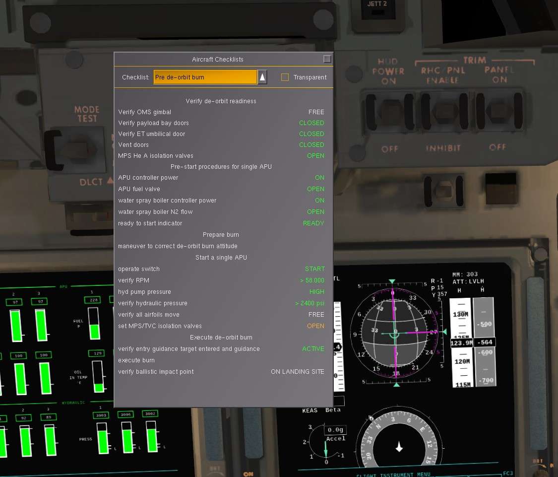
Many of the actions are not mandatory ie. will not influence directly the safety of the flight and return to Earth. If you want to skip some of the actions, you can stick to the In Game Checklists that give you the mandatory items to be done to perform the entry and landing well


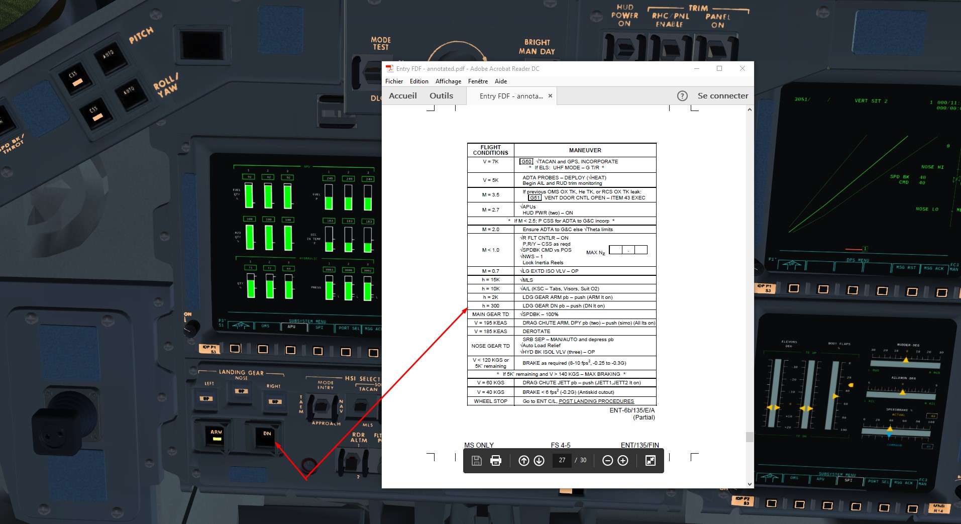
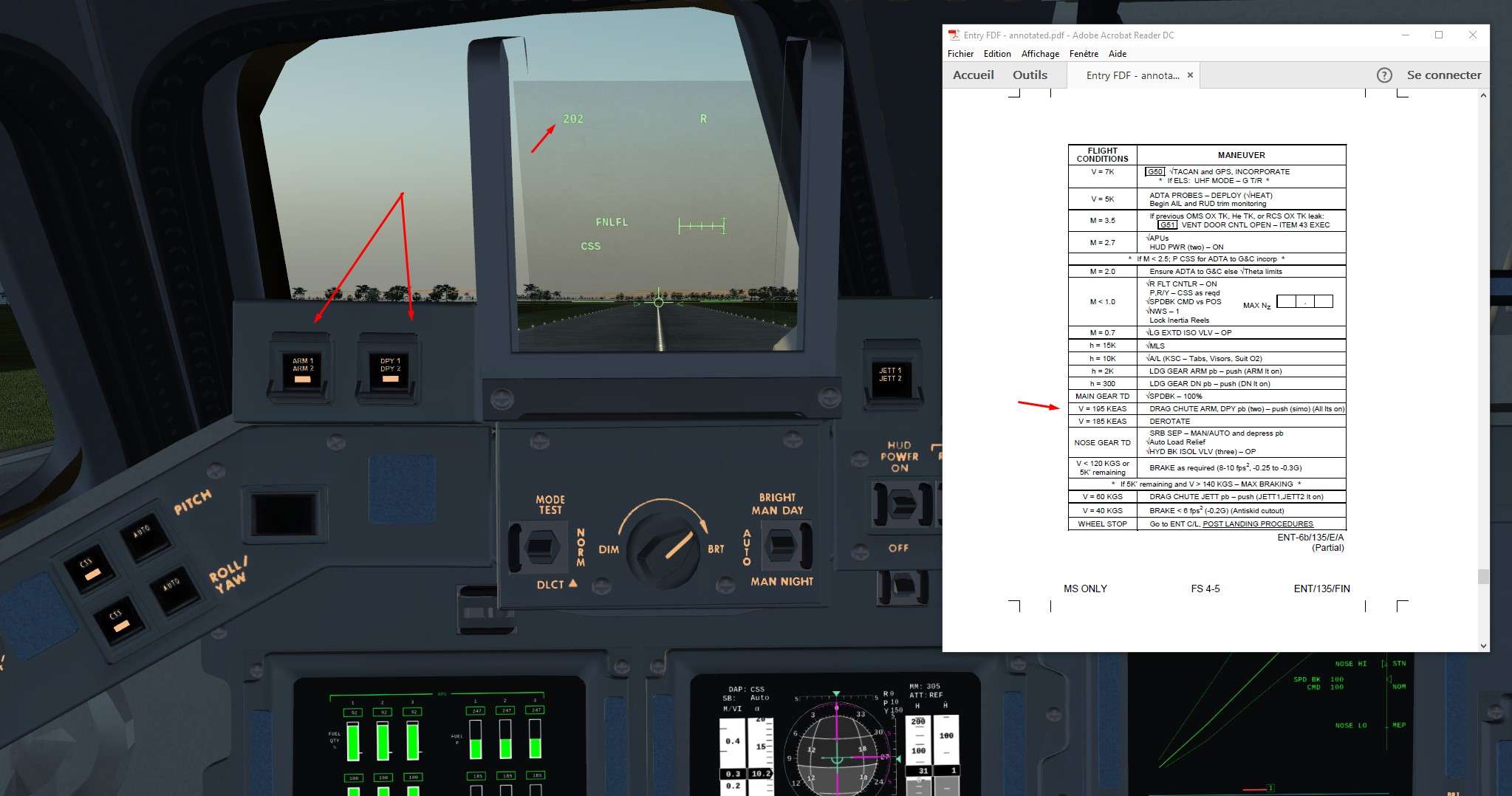
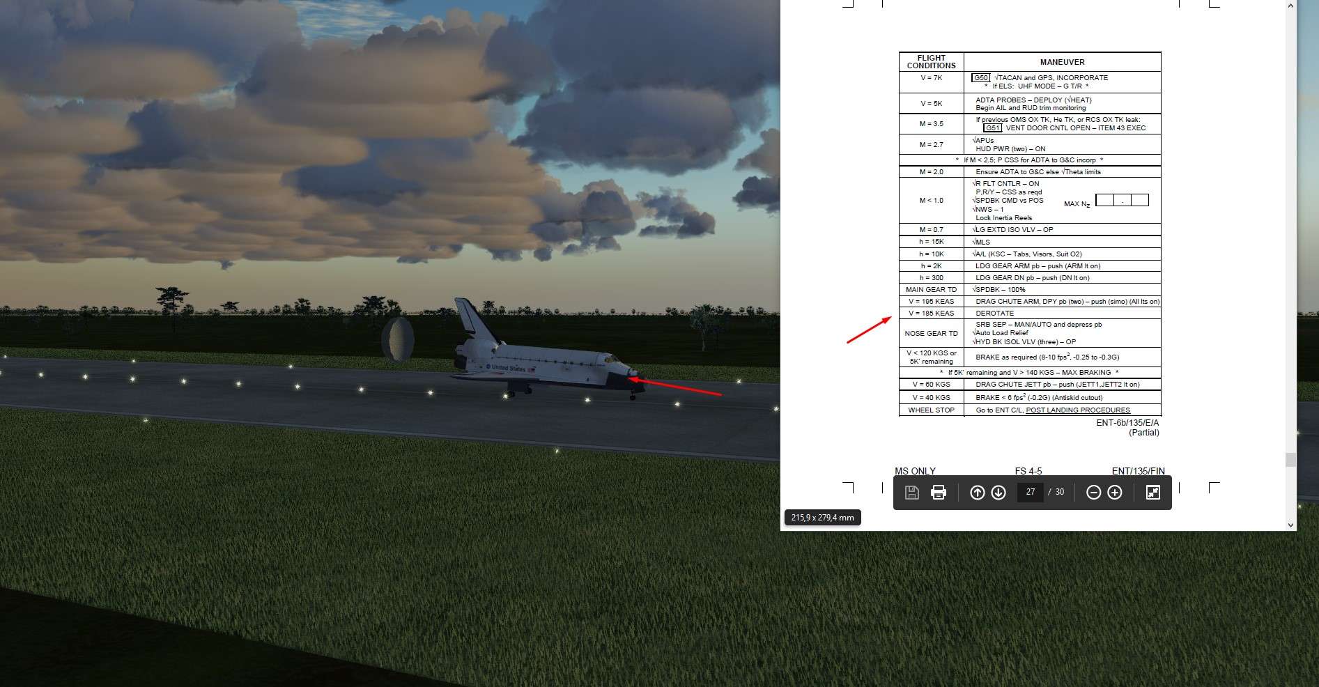
Annotated checklists from real documentation:

Deorbit Preparation https://drive.google.com/open?id=0ByWr8dBBzTv3TlFjbkx5cHRESHM

Entry https://drive.google.com/open?id=0ByWr8dBBzTv3UEFTZTFoUGVWRTA


Small note on GPC and Keyboard procedure
Especially for GPC in advanced mode, there will be a lot of keyboard actions to perform.
To save time, I don't right all the time the end of the sequence


If I use OPS or SPEC function, terminator will be PRO
If I use ITEM or GPC/CRT, terminator will be EXEC


I am a bit lazy, yes


I) Pre Deorbit Procedures


We want to land at KSC, so the scenario will start nearby the destination field to have at least one Orbit to prepare the Shuttle. Earth is rotating, so in one Orbit we will not be exactly overhead KSC if we start right above it at beginning of the mission.
To account of one Orbit of groundtrack drift, we have to start a bit further to the East, around 1000Nm for a 50° inclination Orbit ( like the one of ISS). 1000Nm corresponds to 20° of addition in Eastern Longitude. ( For a 30 ° inclination Orbit, numbers are around 600 Nm of drift for one Orbit, and 10° of East Lon to had.)

Also, we have to specify a Heading. We will take 138° ( 90°+48°) which will place us to a Descending Node ( in regards of Equator reference) at Mission start and allow us to do later the entry overhead the USA instead of Central America

Settings to enter in Launch Menu:

Image


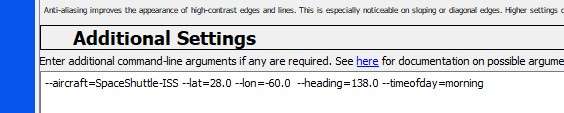
Same Latitude than Landing Site, 20° more in Eastern Longitude than KSC as explained and south east heading.
Little trick here, a heading of 45 ° or 135° places you half way on your orbit, so inclination will be twice the latitude ( here around 50 ° as wanted)
A heading of 90 ° will place at an apogee or perigee, so inclination will be equal to the latitude set.
Be careful if you put a heading of 90 ° to have a latitude equal or higher than the one from landing site. If not, your inclination will be lower than the Landing Site latitude and it will be almost impossible to land there.


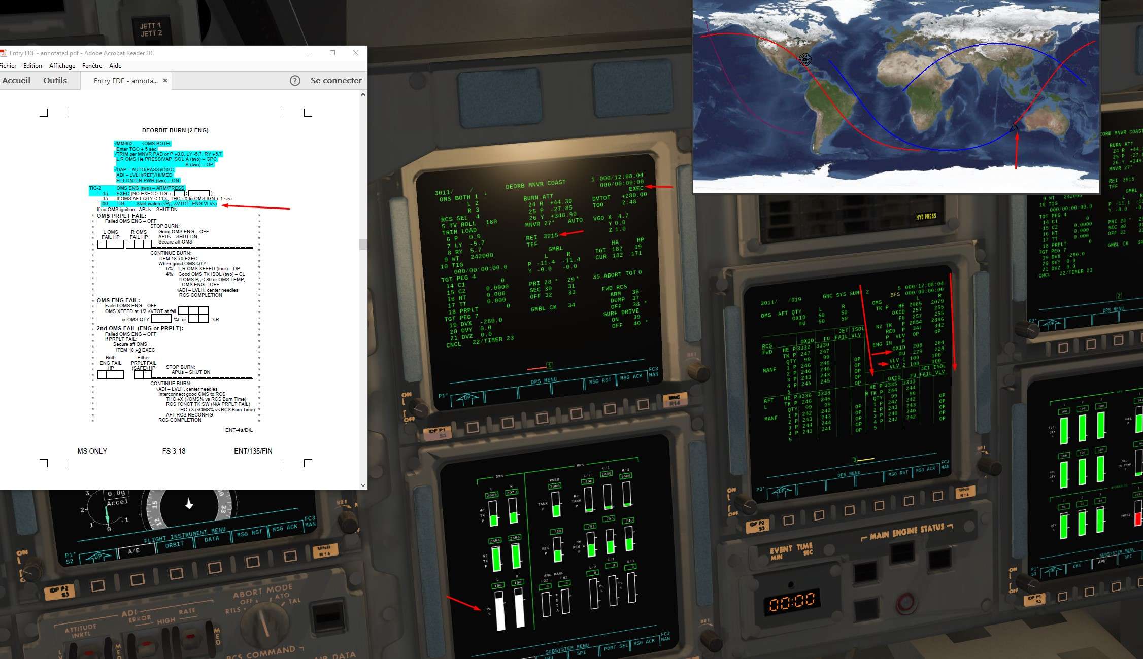
Let's set the good parameters for the landing field in Entry Guidance Computer Window to have some up to date visual clues on the trajectory map.
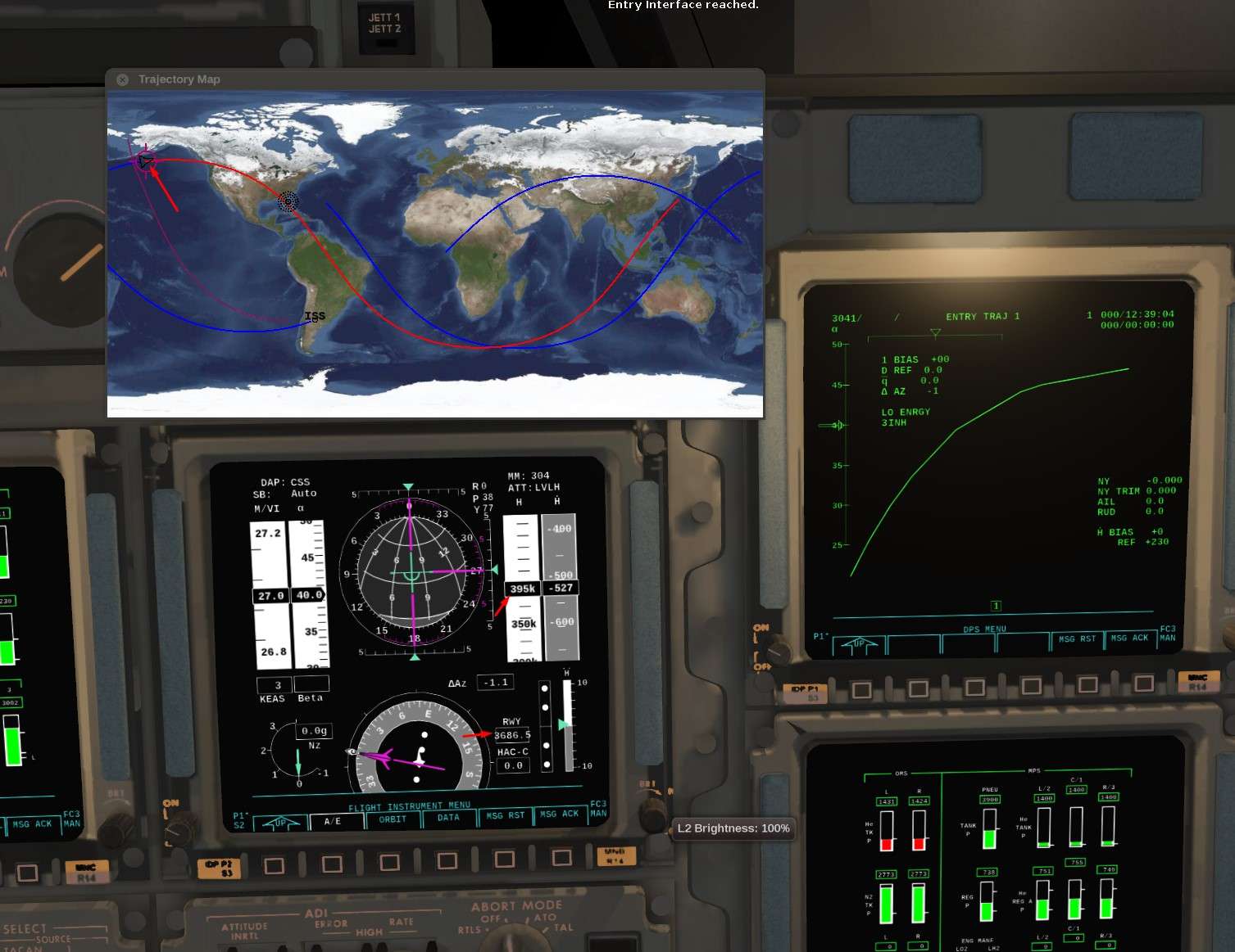
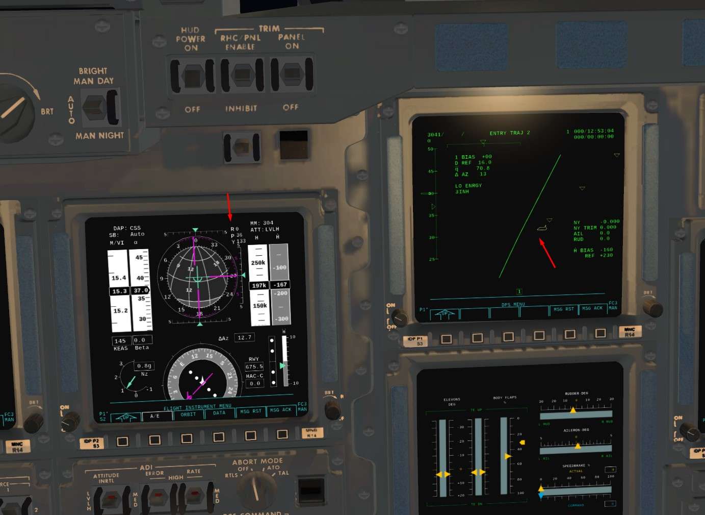
The dark red banana left of the screen shows us the Entry Interface (EI) ( EI begins at 400000 feet). We want it to be ideally at 4100Nm from KSC, I took a bit less around 3900Nm ( Between 3000 and 4000 it's ok, Re entry angle will be a bit steeper but within limits)

Image


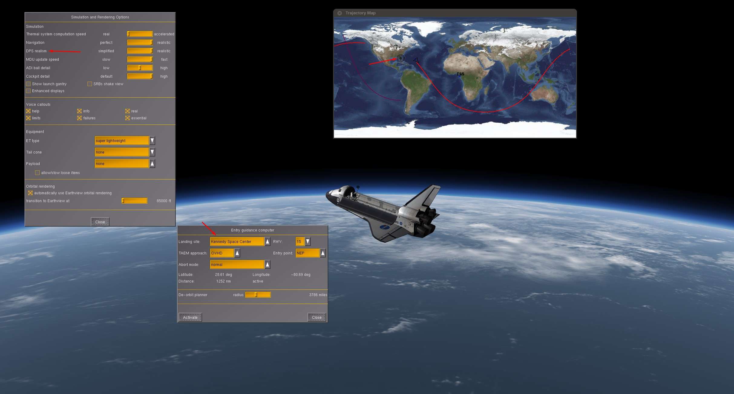
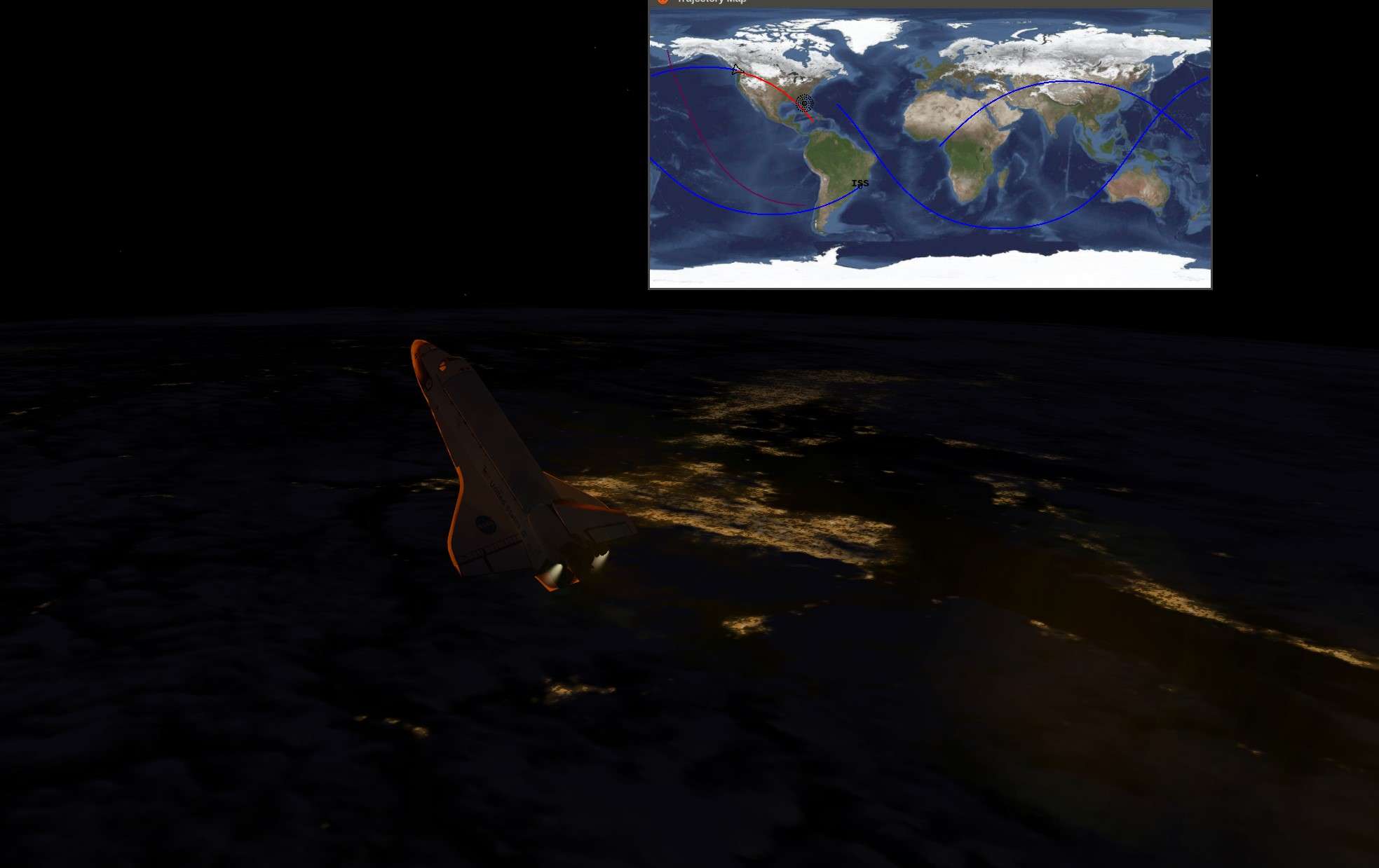
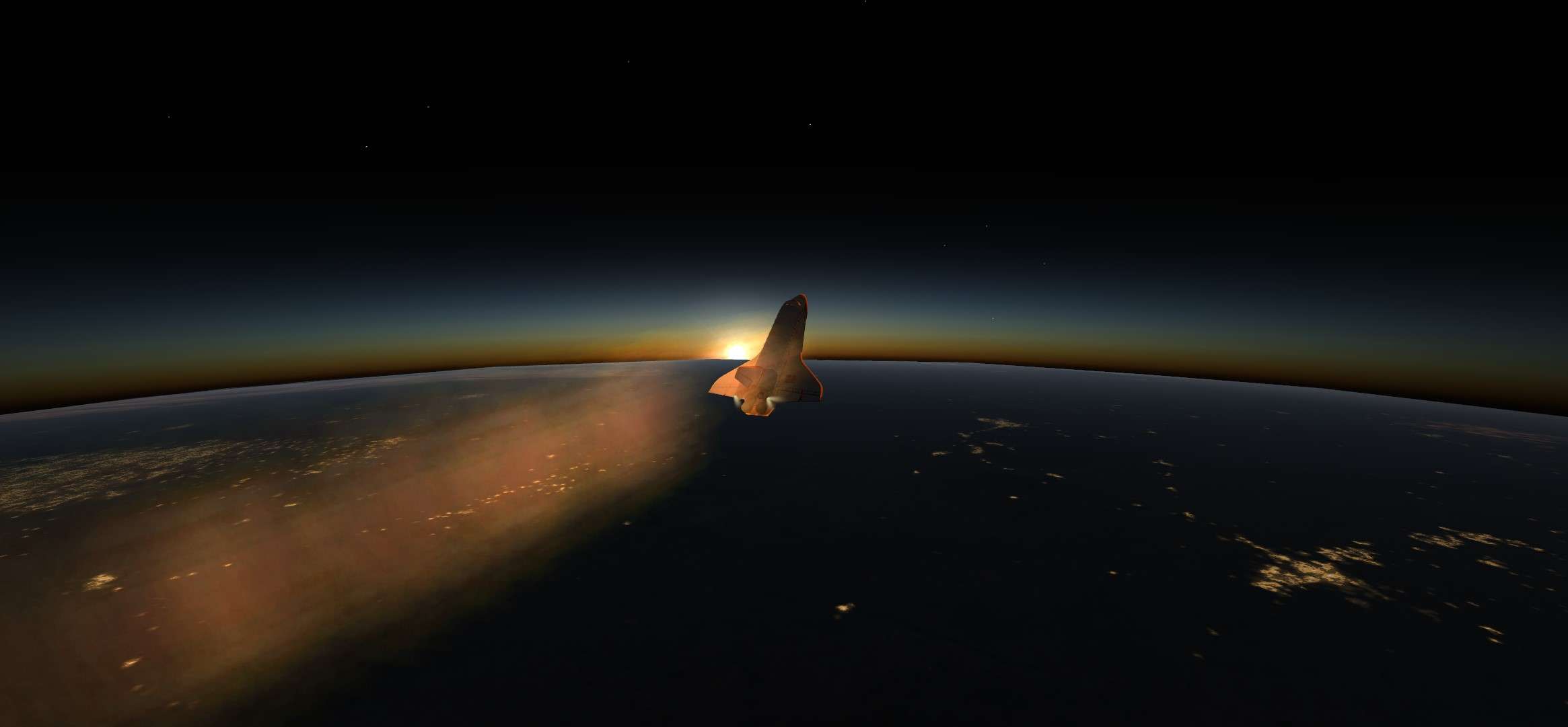
A screen took later int he mission to show some important features in the trajectory map. Blue Orbit with the Shuttle on it is the present Orbit. Red one is the forecasted groundtrack for next Orbit.
We see that starting with a bit more of Eastern Longitude is working well and we gonna overfly perfectly KSC during next Orbit ( hence during entry phase)
It can still vary a bit due to dynamical calculations, but it works great.

Image


Optional Part for Advanced GPC users


For those who use Advanced GPC setting, we have to do 2 or 3 small changes to have the correct configuration in Nominal Bus Assignement Table ( NBAT) in order to do the correct transition towards OPS 3 later on.
Some hints here for better understanding: https://forum.flightgear.org/viewtopic.php?f=4&t=25747&start=1995


We will do a short procedure compared to the full one needed to go from OPS 1 to OPS 2. We have to re assign some bus and put GPC 3 and 5 in sleep mode
Once done, you can save the state. GPC configuration is well supported by save state and you can use this save as a strating point for future missions.

Let's go for 3 mn of work in Slow time compression


Spec 0 Item 9 +1 Item 10 +2 Item 14+2 to deassign GPC 3 from its bus
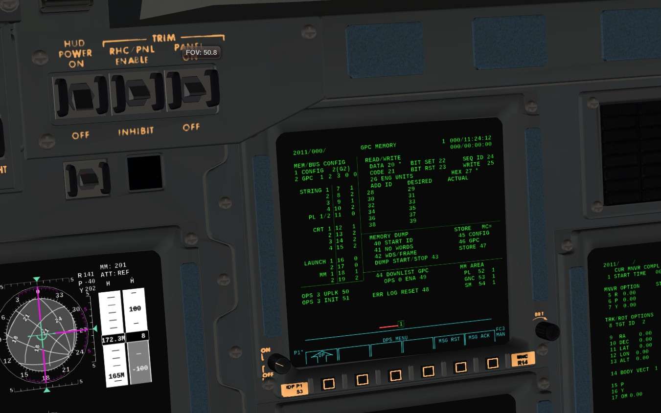
Image


Results

Image


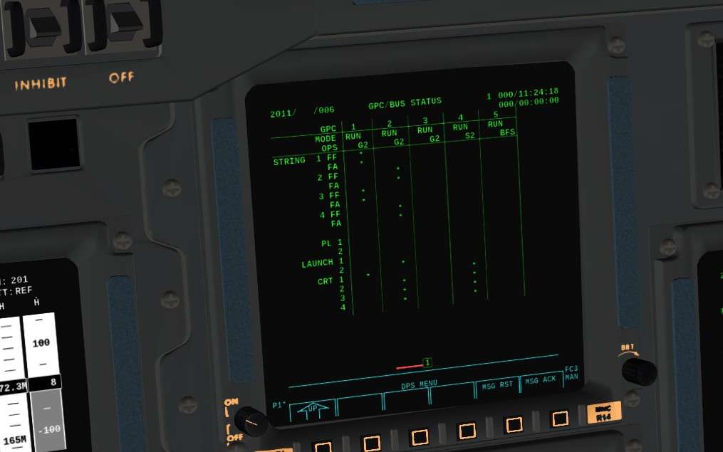
Then we bring GPC 5 BFS on the central Display CRT 3 with BFC Display switch on pedestal and we put it in system software only OPS 0

Image


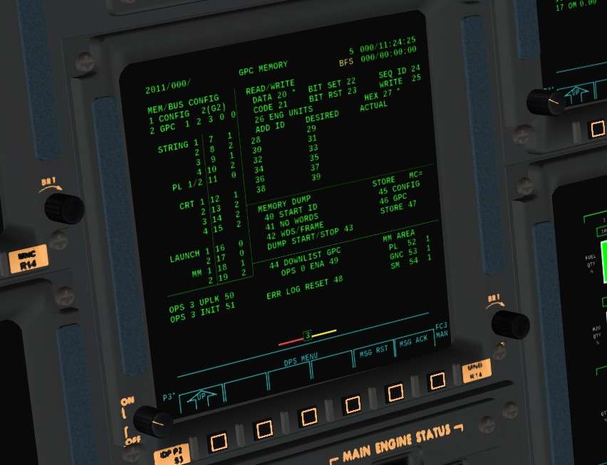
GPC 3 and 5 in Halt mode, GPC 4 in Terminate Output

Image


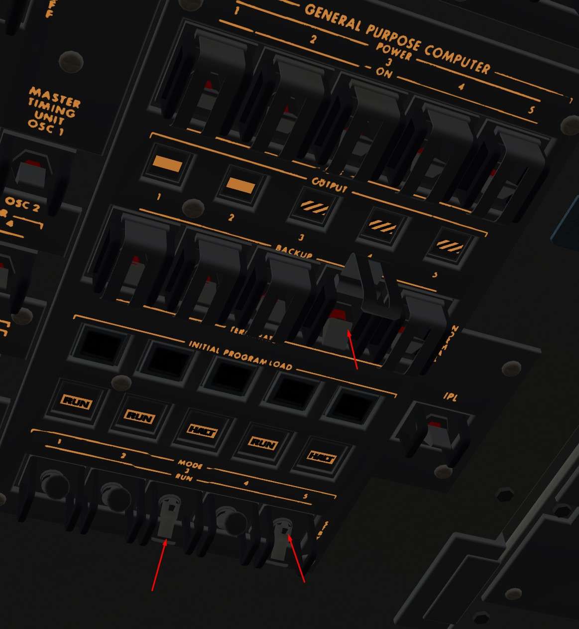
CRT 3 off and Spec 6 to check good Bus assignement

Image


That's it, done

End of optional part


Let's go!


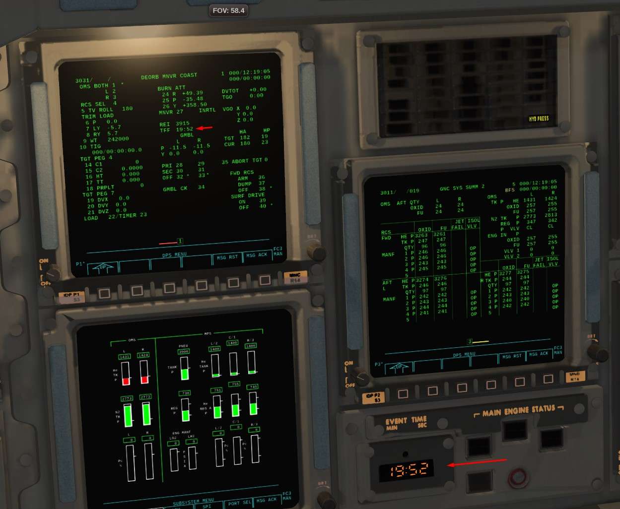
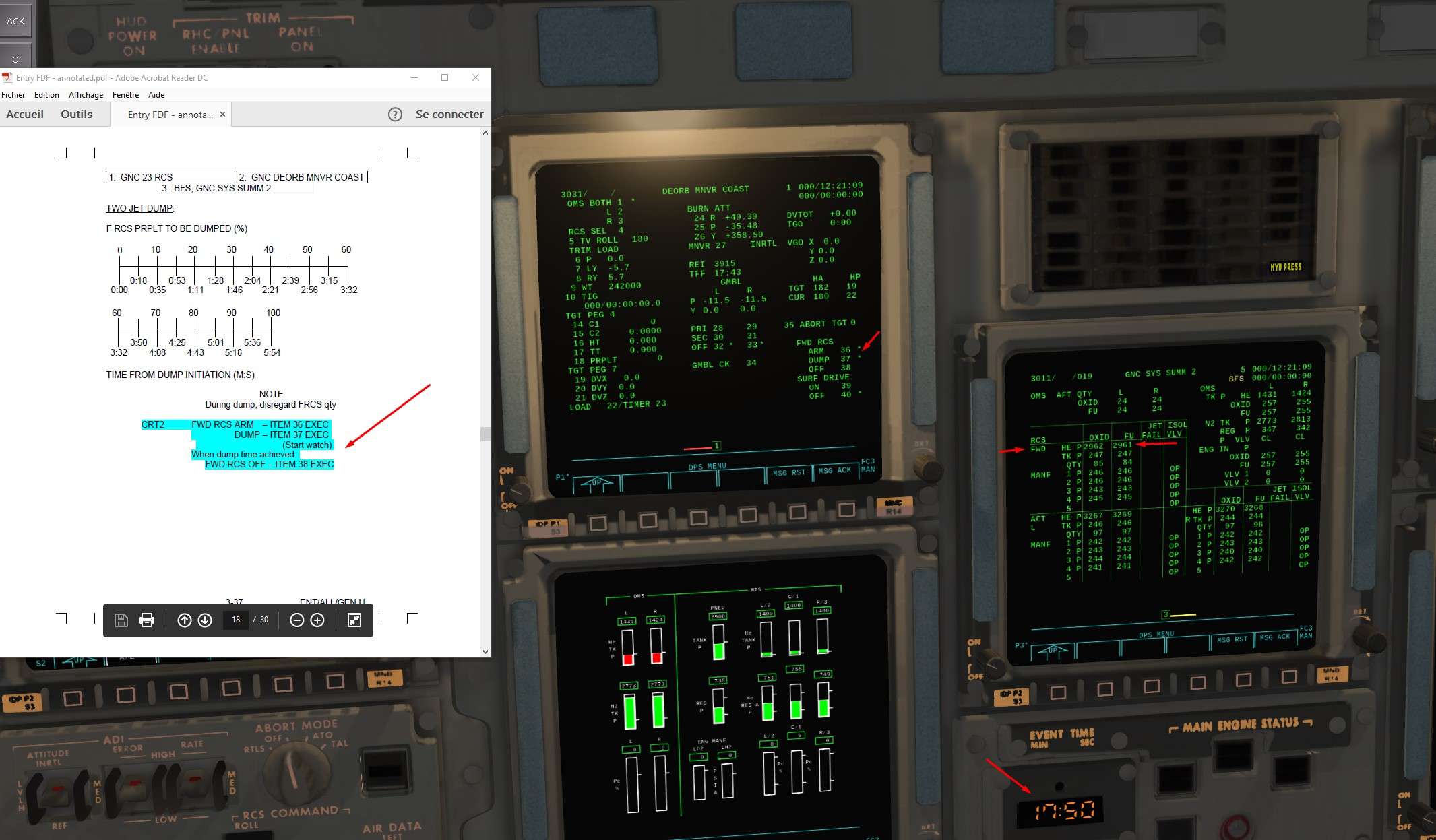
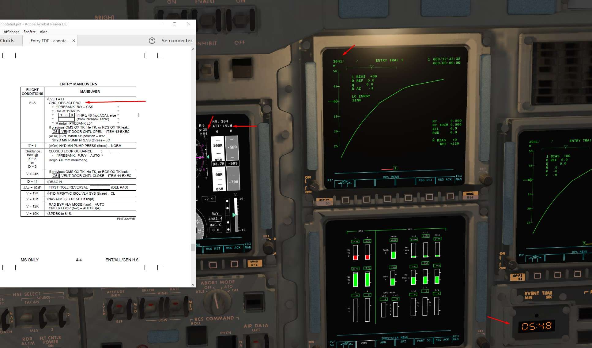
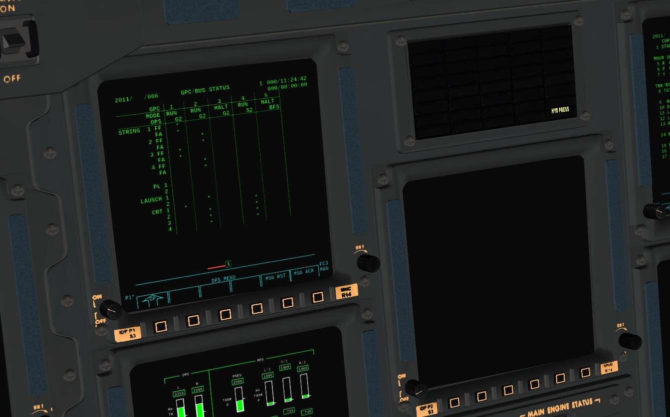
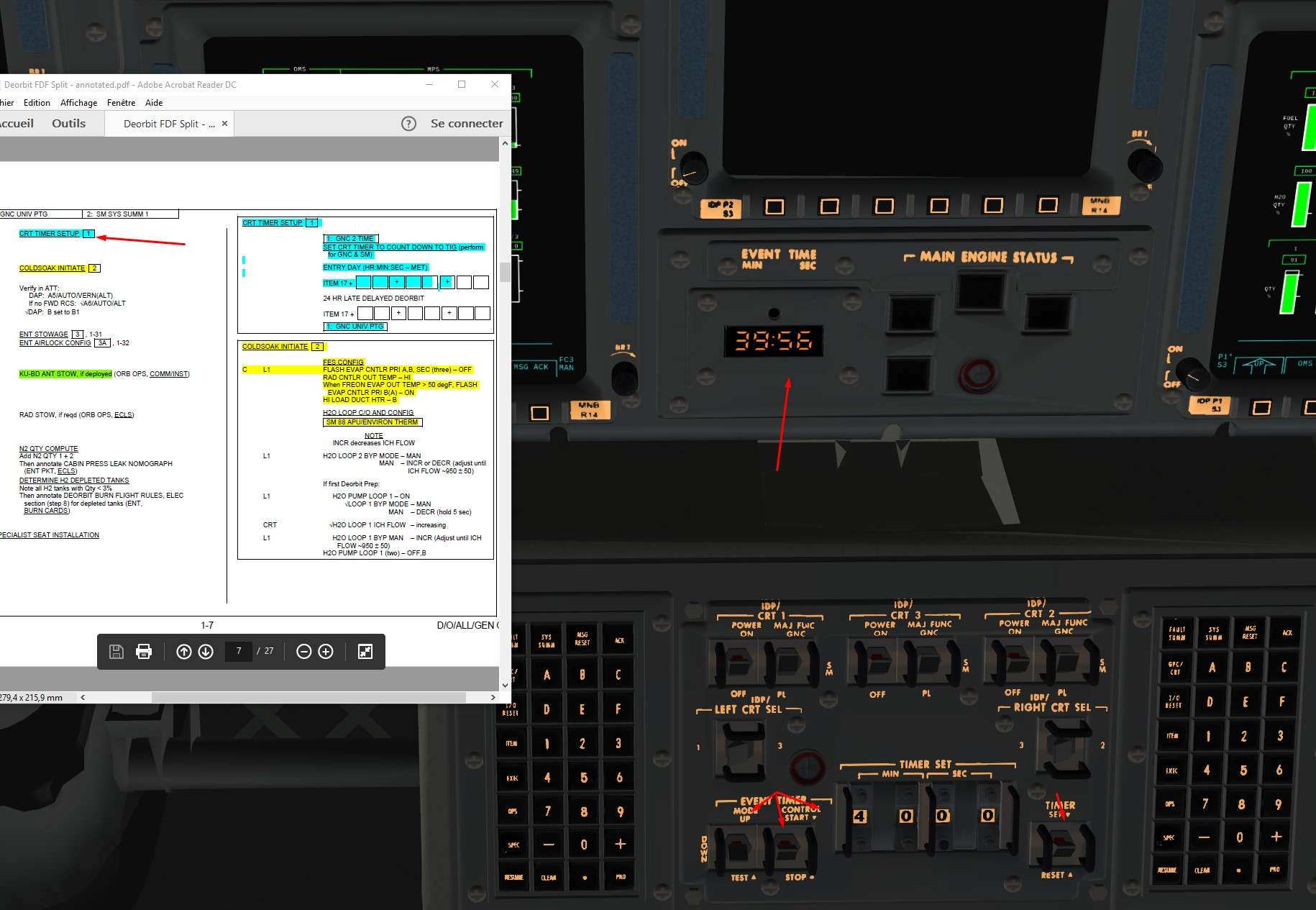
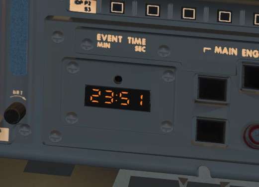
1) We set up the timer on the time remaining before De orbit burn. ( 4h in real, 45 mn for us to have the burn in a half Orbit in order to create a Perigee overhead KSC)
We can do it via SPEC 2 bringin us to a complex page to handle timer, or you can do it ( like in the screen) directly on the Central Event Time, more practical I find.
It is nice also to handle your time compression and know how much time you have to finish preparation before the burn ( and you can adjust time compression in consequence)

Image


2) Cold soak Procedure Then, I love that name.
Process is to cool the Freon in the radiators and to stock in it.
Thermal management in the sim is really well done, and there is some differences with the real procedure due to the huge complexity of a thermal model in a space craft like the Shuttle, where dozens of systems are exchanging heat.
In game procedure will be then a bit shortened.


For the most Curious, some lines about what happens in reality.

The Freon going out of the radiators will join the general Fron Loop ( hot) in order to cool it. In normal mode, Freon in the main loops has to be cooled down around 39 °F after the cold Freon from Radiators is mixed with the hot one

For the Cold Soak Procedure, we switch the Feon Out Temp mode into Hi. Now, the target temperature for Freon cooling is raised to 57 °F instead of 39 °, hotter so.
Hence, the flow of Feon in radiators will be slower, we need less cold Freon to cool the main Loop. This slow flow will have the consequence to cool more than usual the Freon (stagnating) in the radiators, it is the cold soaked. To sum up, with less cooling required in Main Freon Loop, the Freon in the Radiators becomes cooler because it stays more time in them.
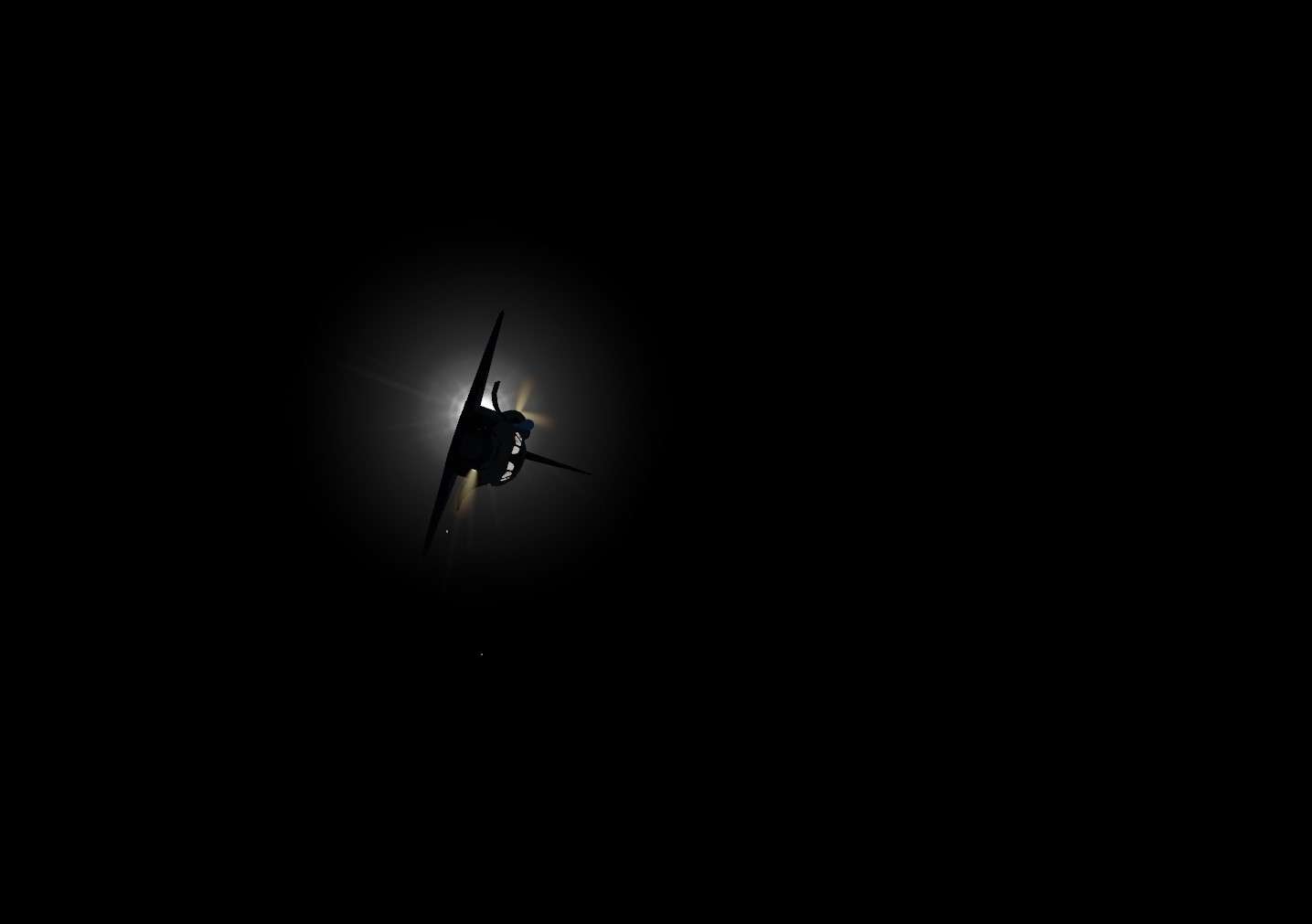
Also, Shuttle move into a Tail to Sun attitude ( tail of the shuttle pointing towards the Sun) to have the radiators in the Shadow.

1 hour after the beggining of that procedure, Freon in the Radiators will be stocked in it and save for later. To do that, Radiators are By Passed and Freon Loops are isolated from Radiators)
Cooling will be now into the hands of the FES that will be re activated for the last hours of Orbit Operations


Now how it works in the sim.
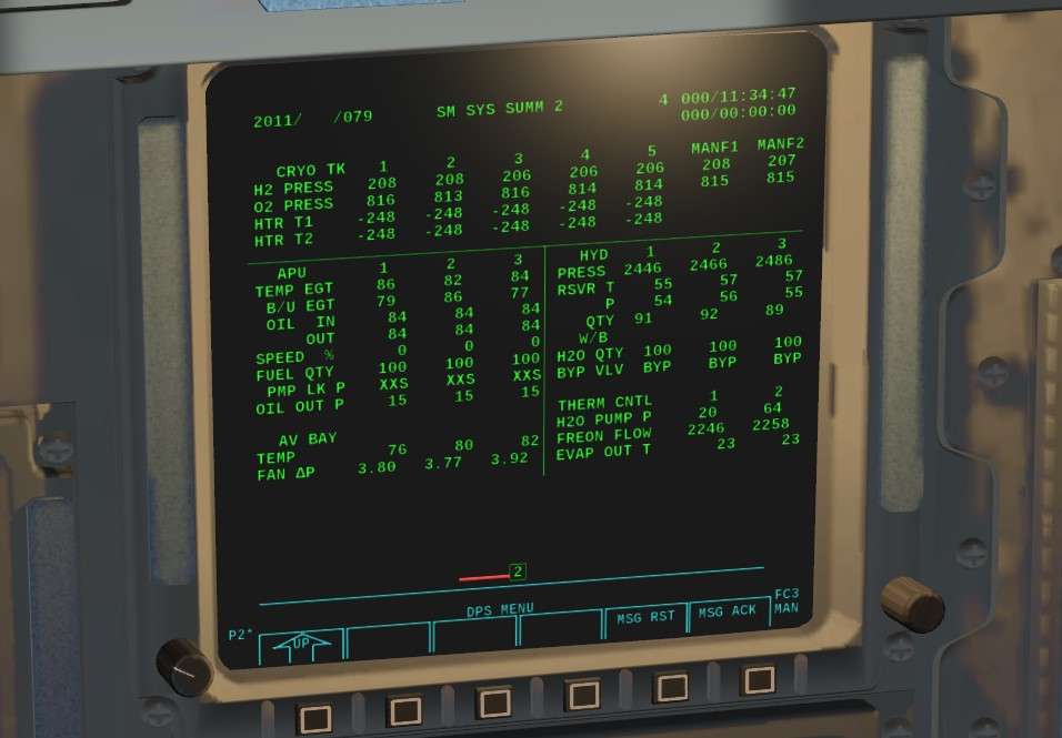
We check that FES are off and we switch Radiators to Out Temp Hi

Image


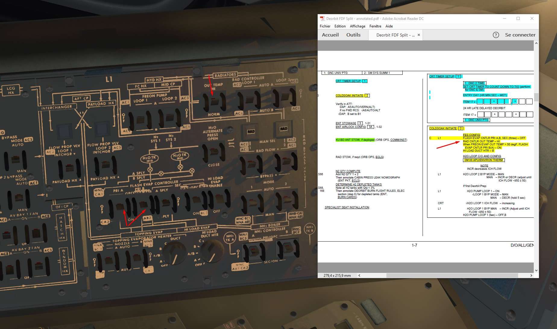
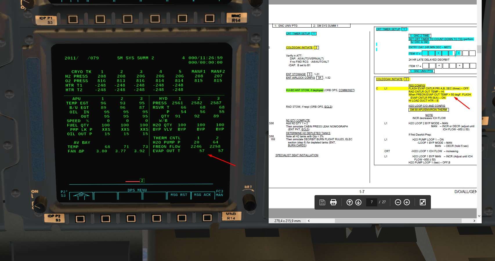
A quick glance on Freon Evap Out Temp Spec 79 in SM Mode ( Value is quite perfect in the example, it can vary a bit, but below 70 ° is fine )
This value reflects temperature of Freon Main Loops after their cooling through Radiators and FES. FES are not active yet, so value indicates the Freon Temp after cold Freon going out of Radiators mixes with Main Freon Loop


Image


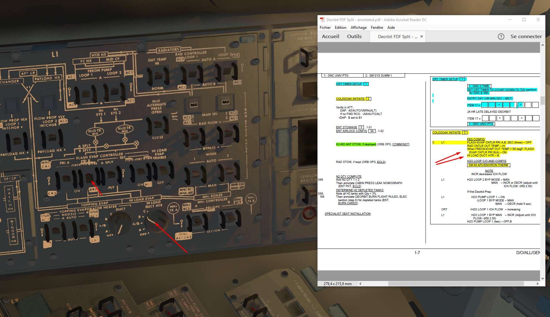
We activate then FES ( primary A or B for differents water tanks supply) Primary A supplies FES with A or B (normally only B) water tanks, Primary B with C or D (normally only D) water tanks if the cross over valve between tank A,B and C,D is closed.
Also we activate heaters fo Hi Load Evap Duct to avoid freezing

Image


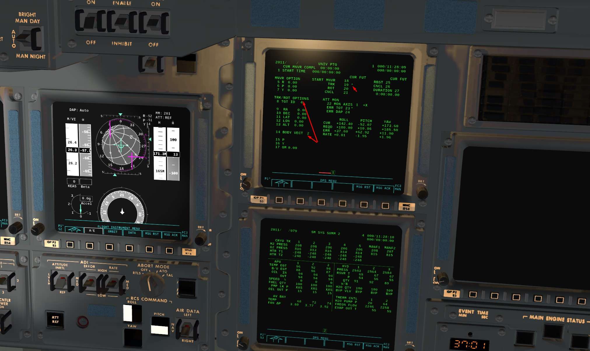
We will go into Tail Sun attitude using the OPS 201 UNIV PTG

Item 8+4 to choose Suns as target
Item 14 + 2 to choose -X shuttle axe as a reference ( Tail)
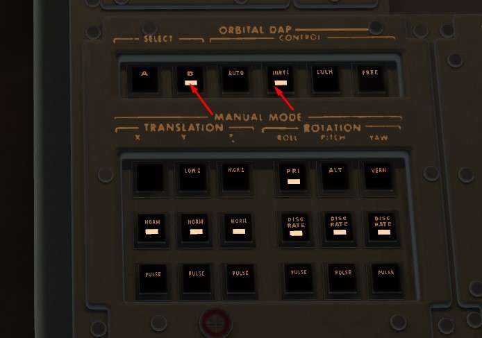
Item 19 and DAP Auto to track the wanted attitude

Once in correct attitude, we can do ITEM 21 to cancel the track and go back in DAP inertial to maintain a nice Tail Sun inertial attitude. It will save some RCS fuel, track function is quite fuel consuming

Image


Image


Result

Image


We stow Ku Antenna

Image


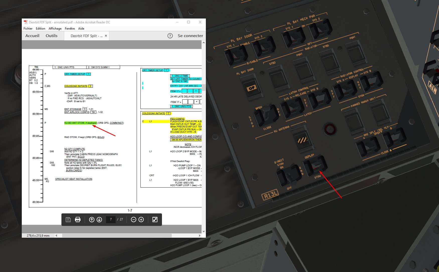
And we open ( closed) the breakers associated with the Ku antenna

Image


3)We check that the GPC running the BFS can display its data on the a CRT ( 3 by convention)
Let's put the GPC 5 back to life with STBY mode.

Image


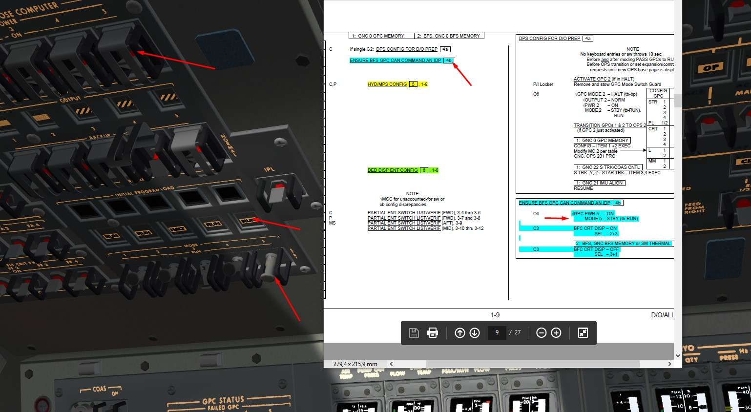
BFC CRT display On to view its data on CRT 3

Image


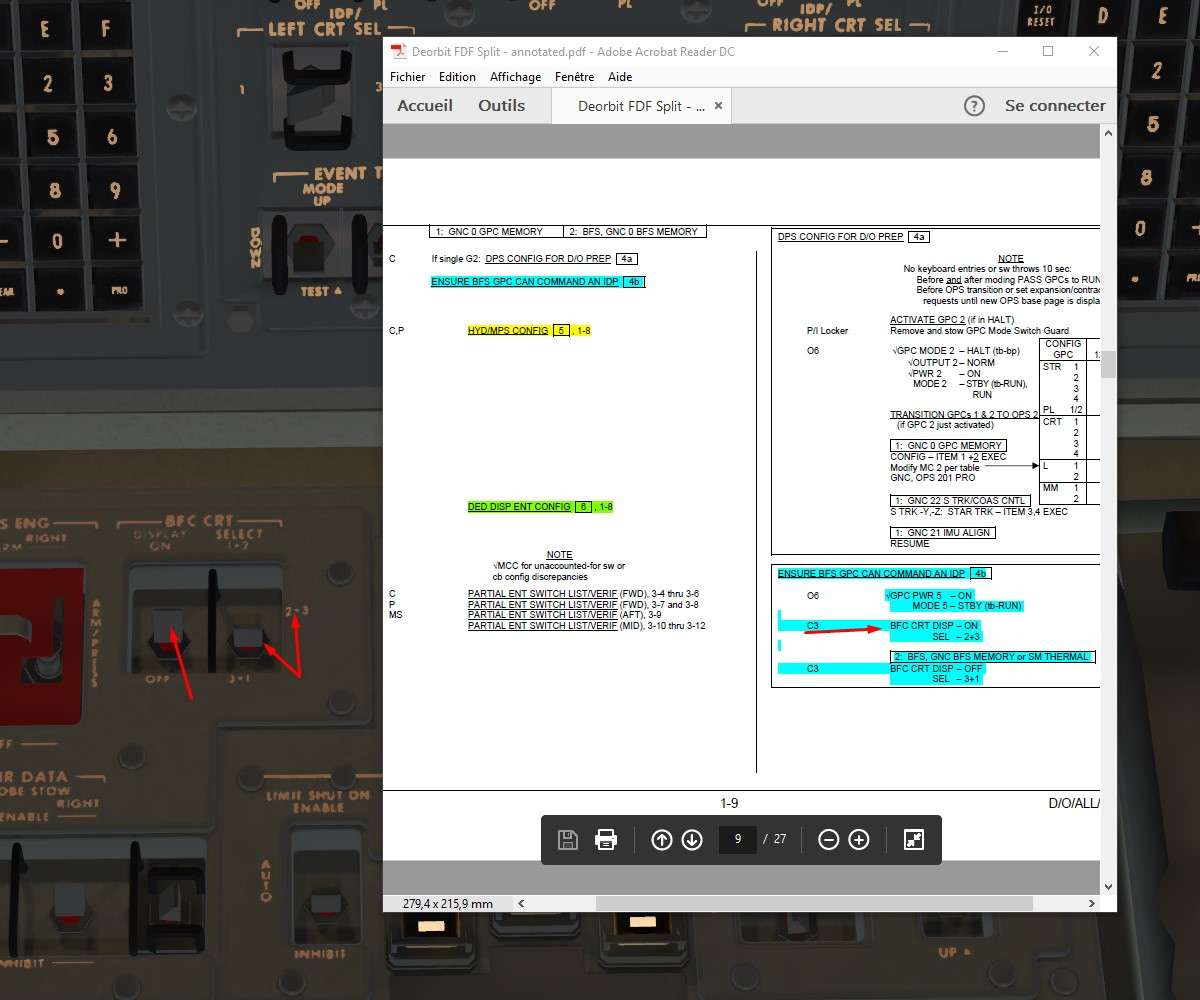
We check that on CRT 3 we have GPC5/BFS in OPS 0 memory mode

Image


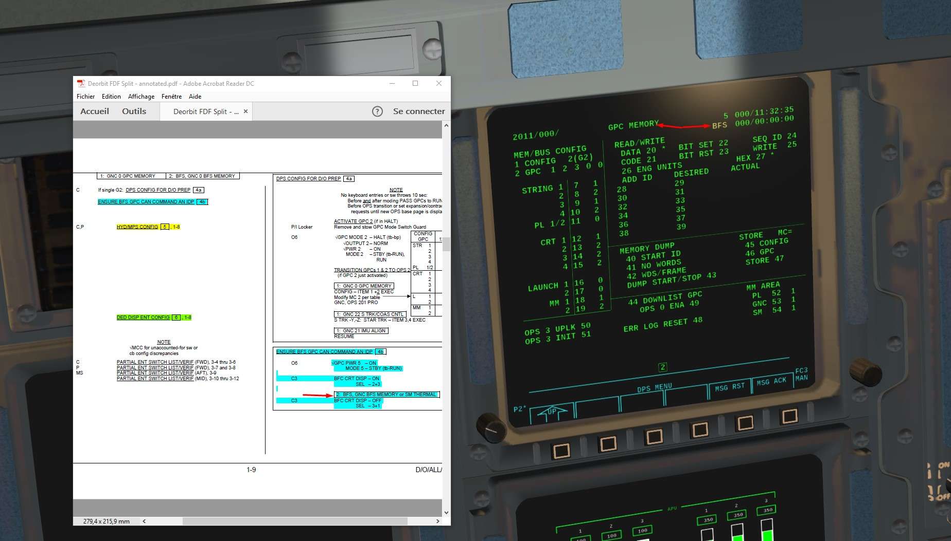
Then reverse step, we switch back to Off the BFC CRT switch display.


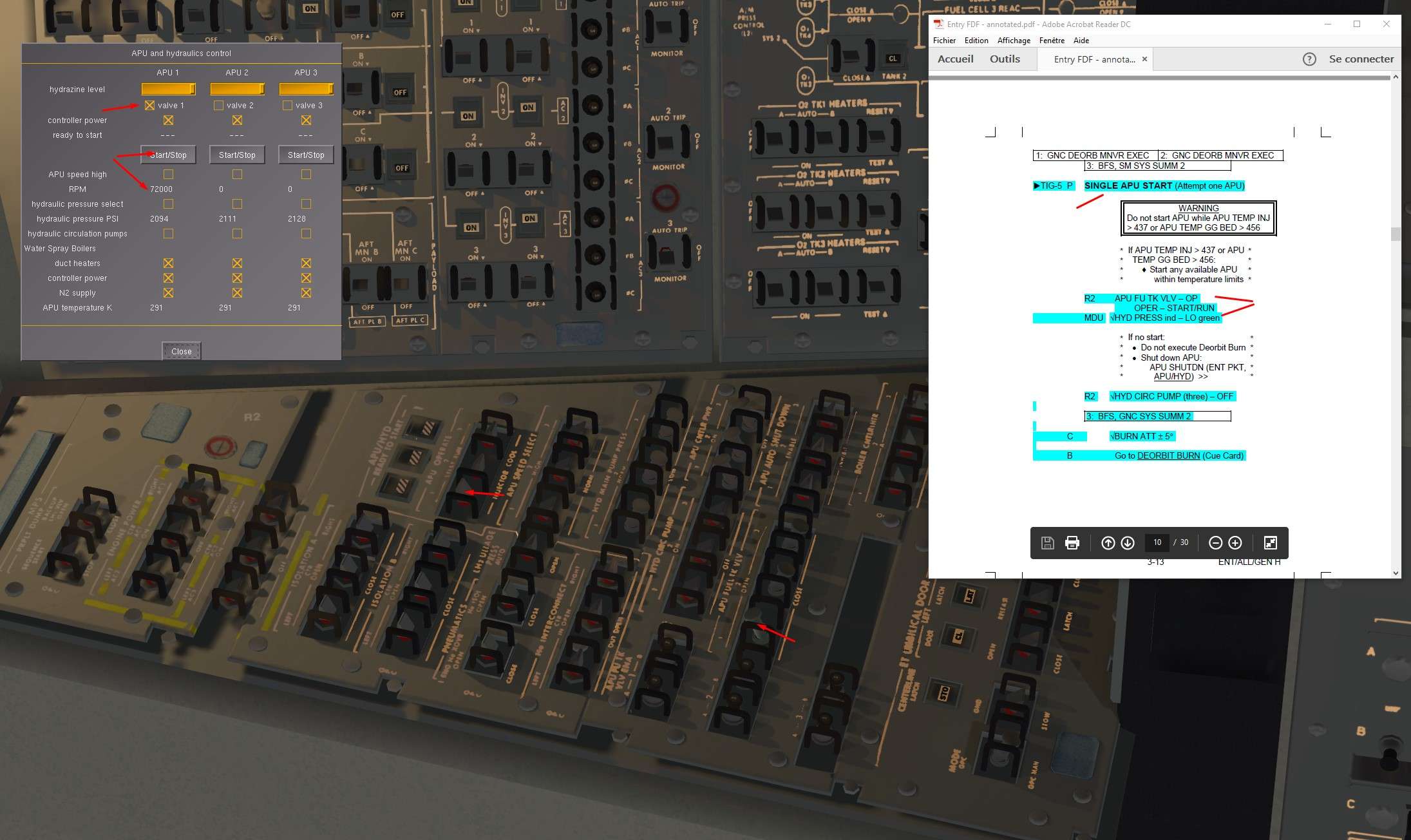
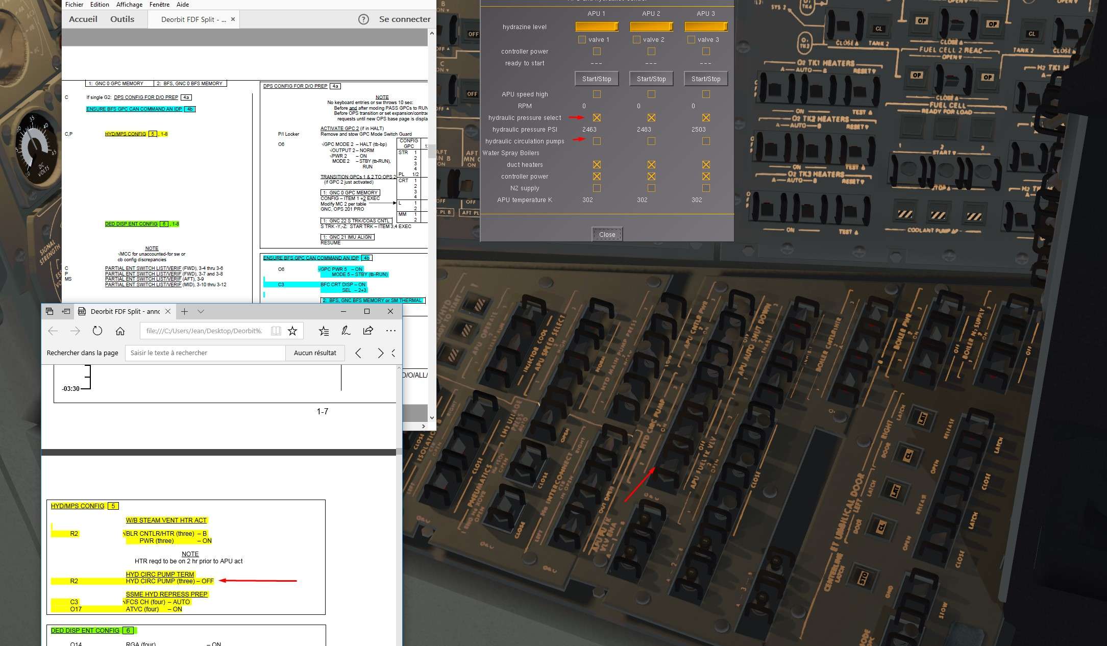
4)Some Hydraulics reconfiguration
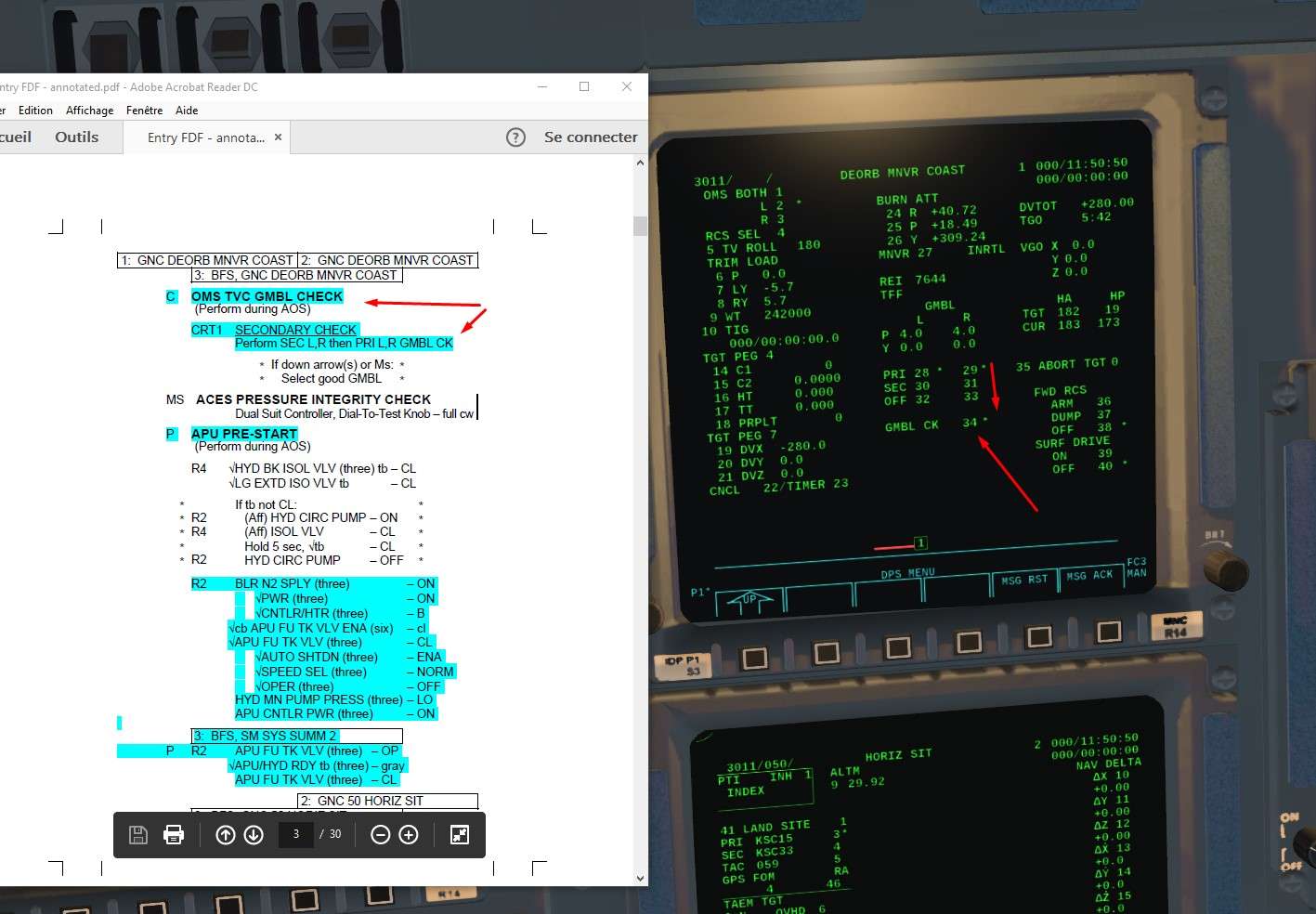
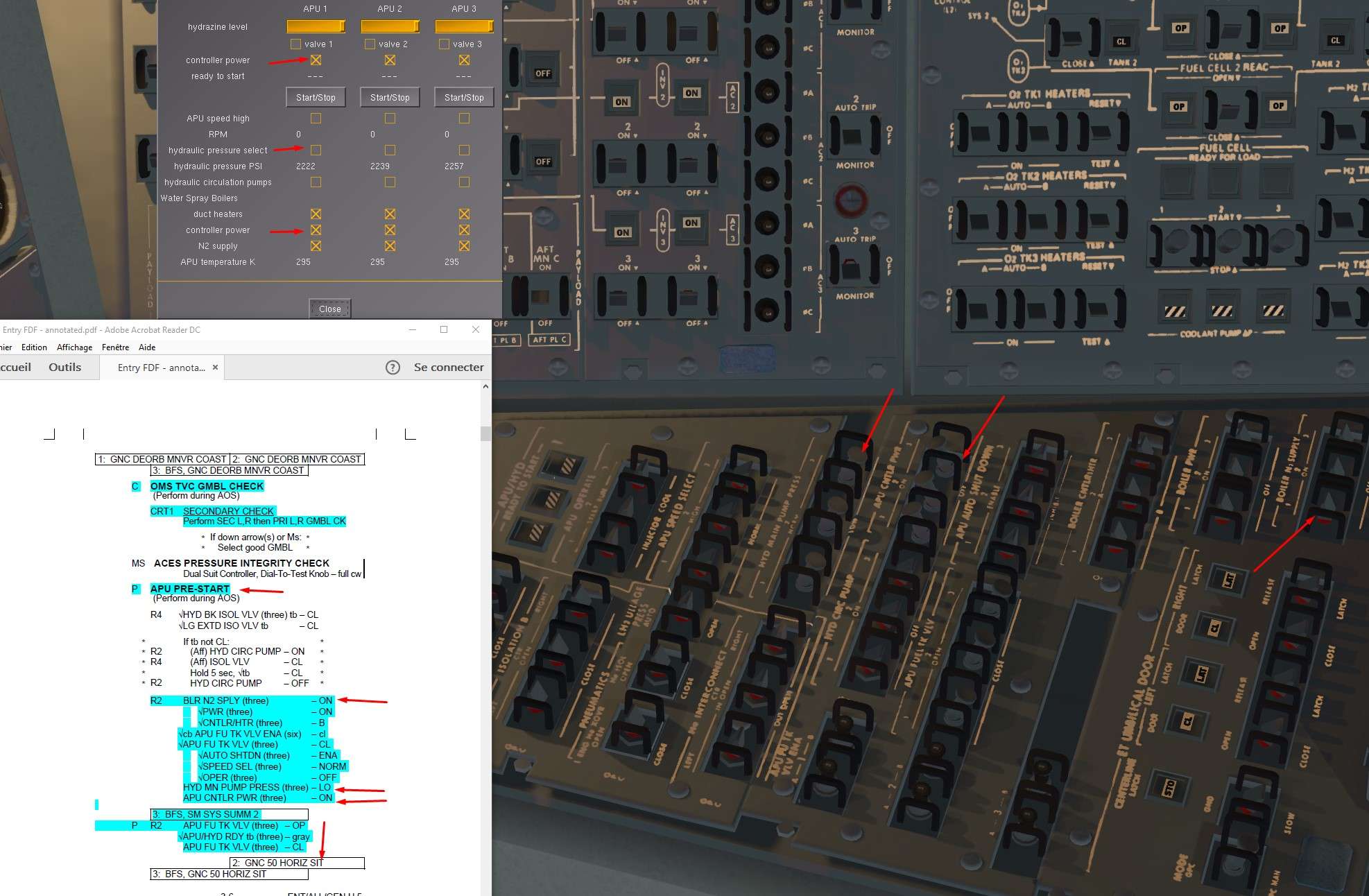
We check that the Wtaer Boilers Heaters are On and we activate their controllers

Image


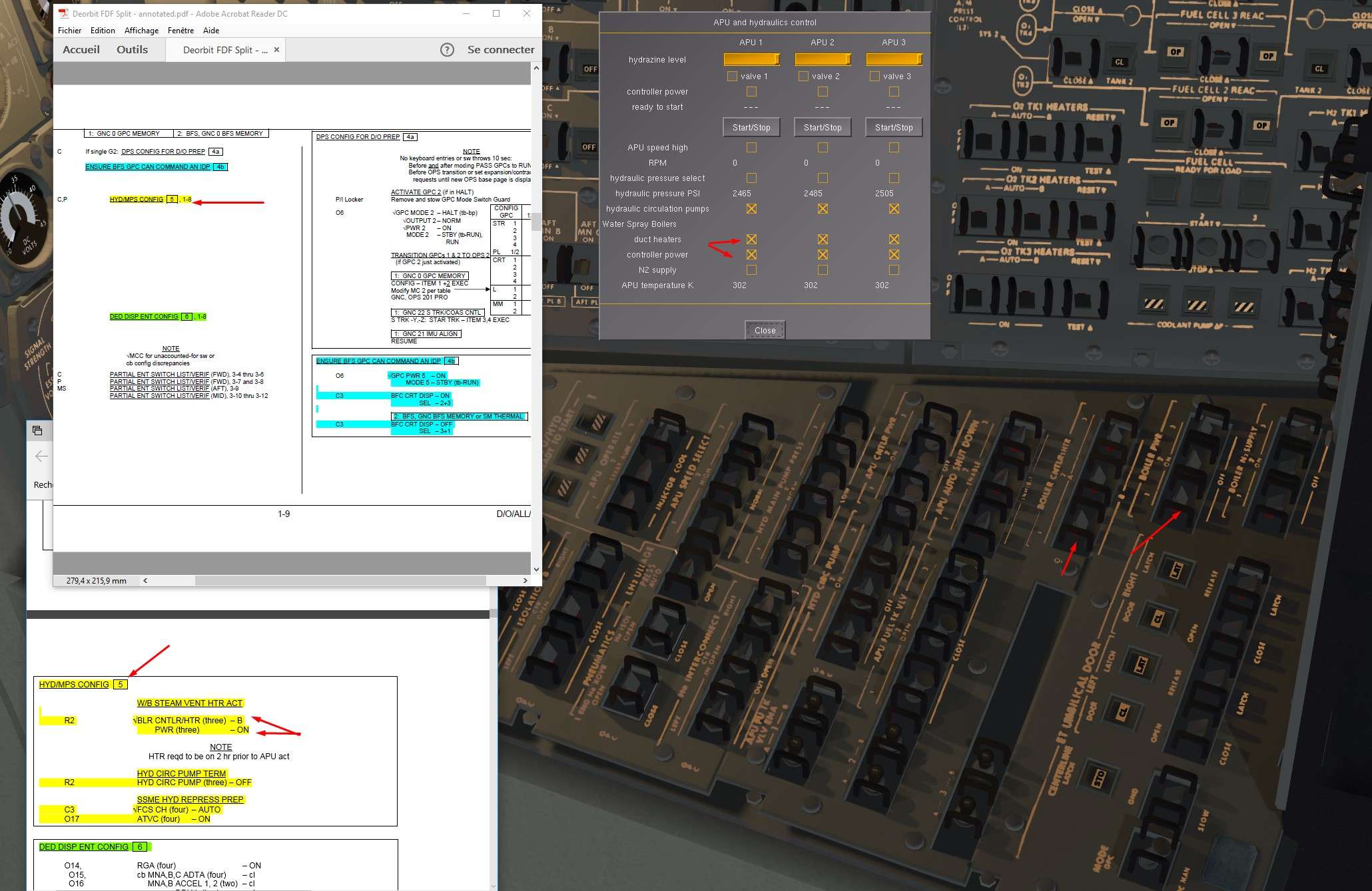
Recirculation Pumps are switched Off, just a few hours before entry, no need anymore for Hydraulic Thermal conditionning of Hydro activated Shuttle parts.

Image


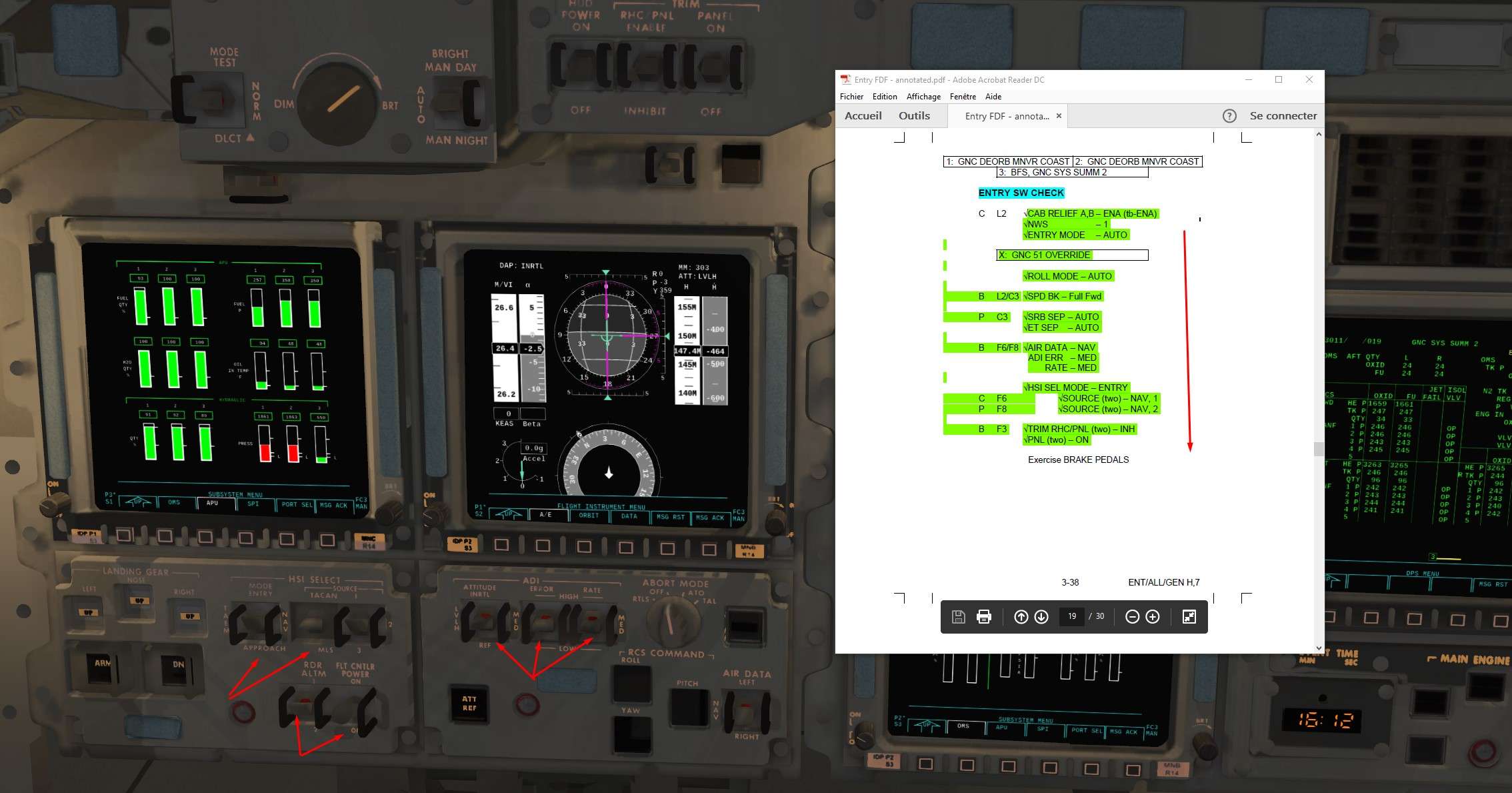
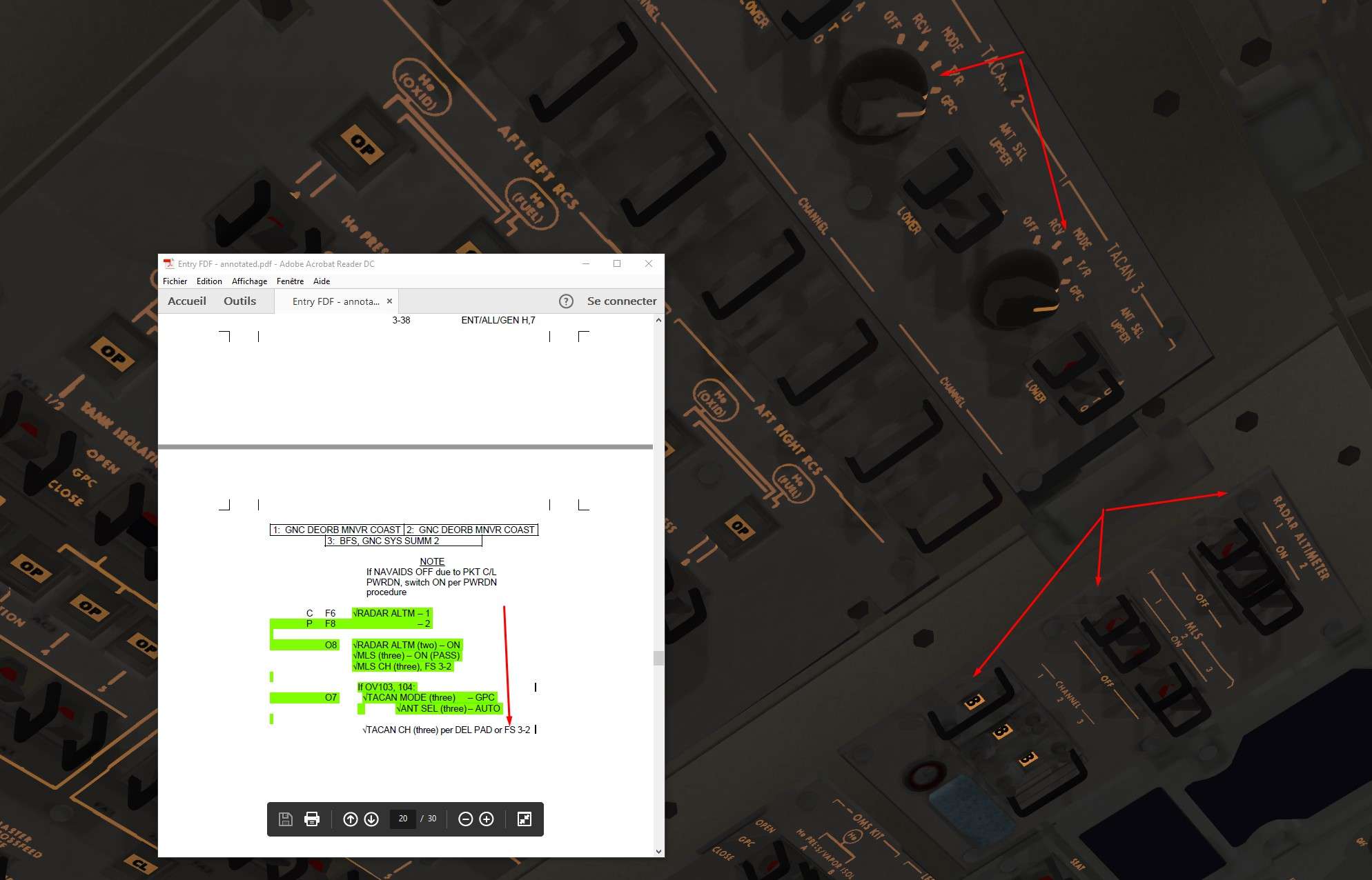
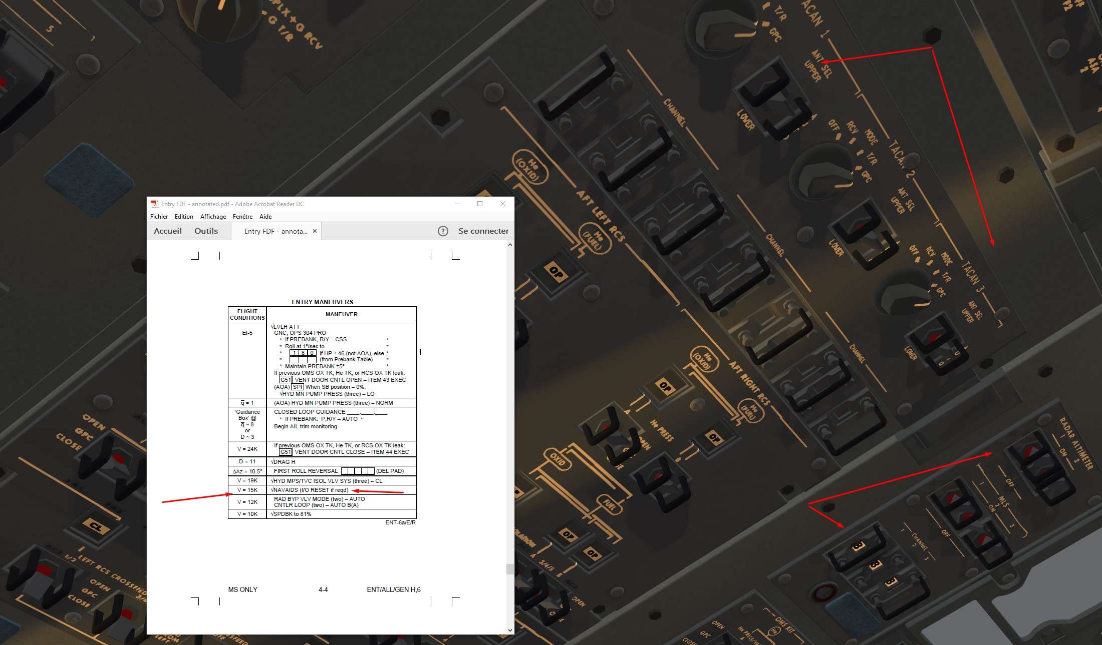
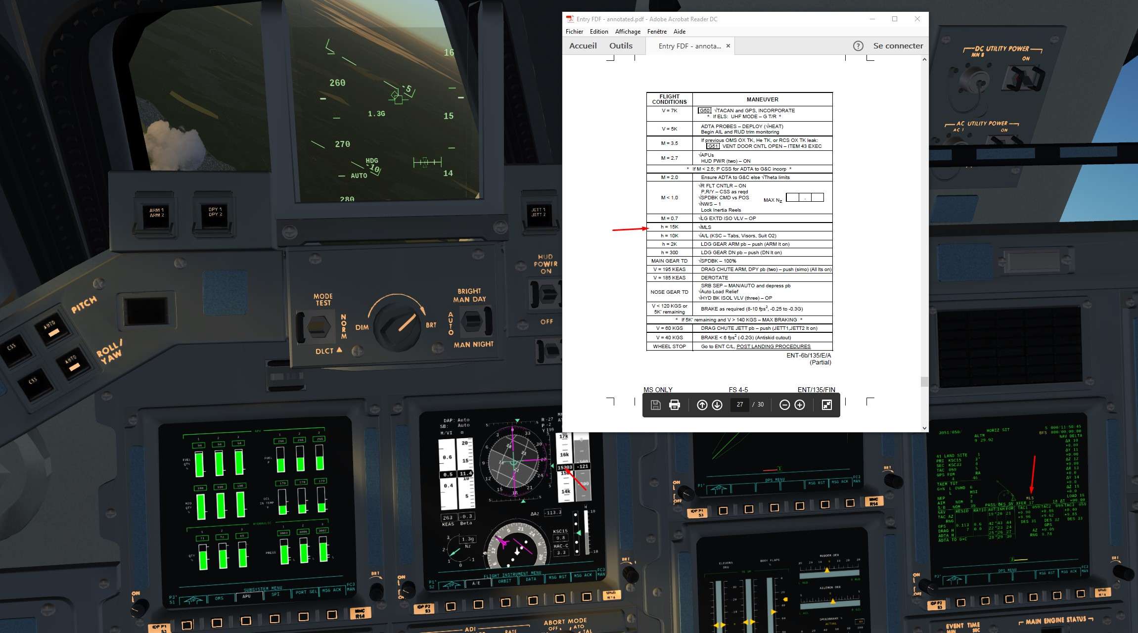
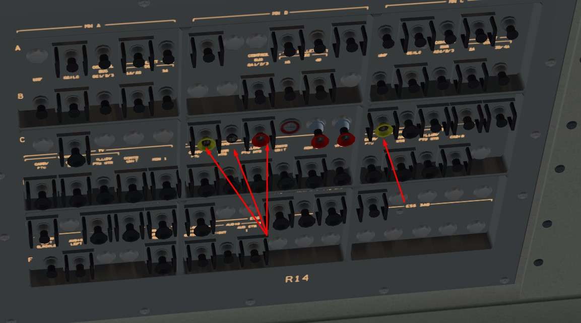
5)Time for Navaids to be back on lin.
Tacan, Radio Altimeters and MLS are switched On ( and correct channels for MLS ie. 8 for KSC runway 15)

Image


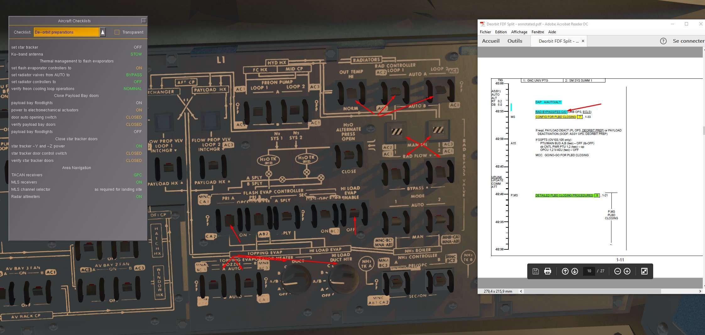
6) Back to the Cold Soak Procedure
We By Pass the radiators by isolating them from main Freon Loops. Small portion of cold Freon will be stucked in the radiators.
We activate also the Hi Load capacity of FES ( and associated heaters) to allow a more efficient Freon Cooling

In reality, Astronauts had to check also the good Behavior of the Secondary FES, which works a bit differently ( cooling the Freon at 62 ° instead of 39°).
Aim here was to test it to avoid further maintenance actions on the ground during turnaround of the Shuttle. Easier to test it in Orbit than on the ground I guess.

Image


Temperature looks good

Image


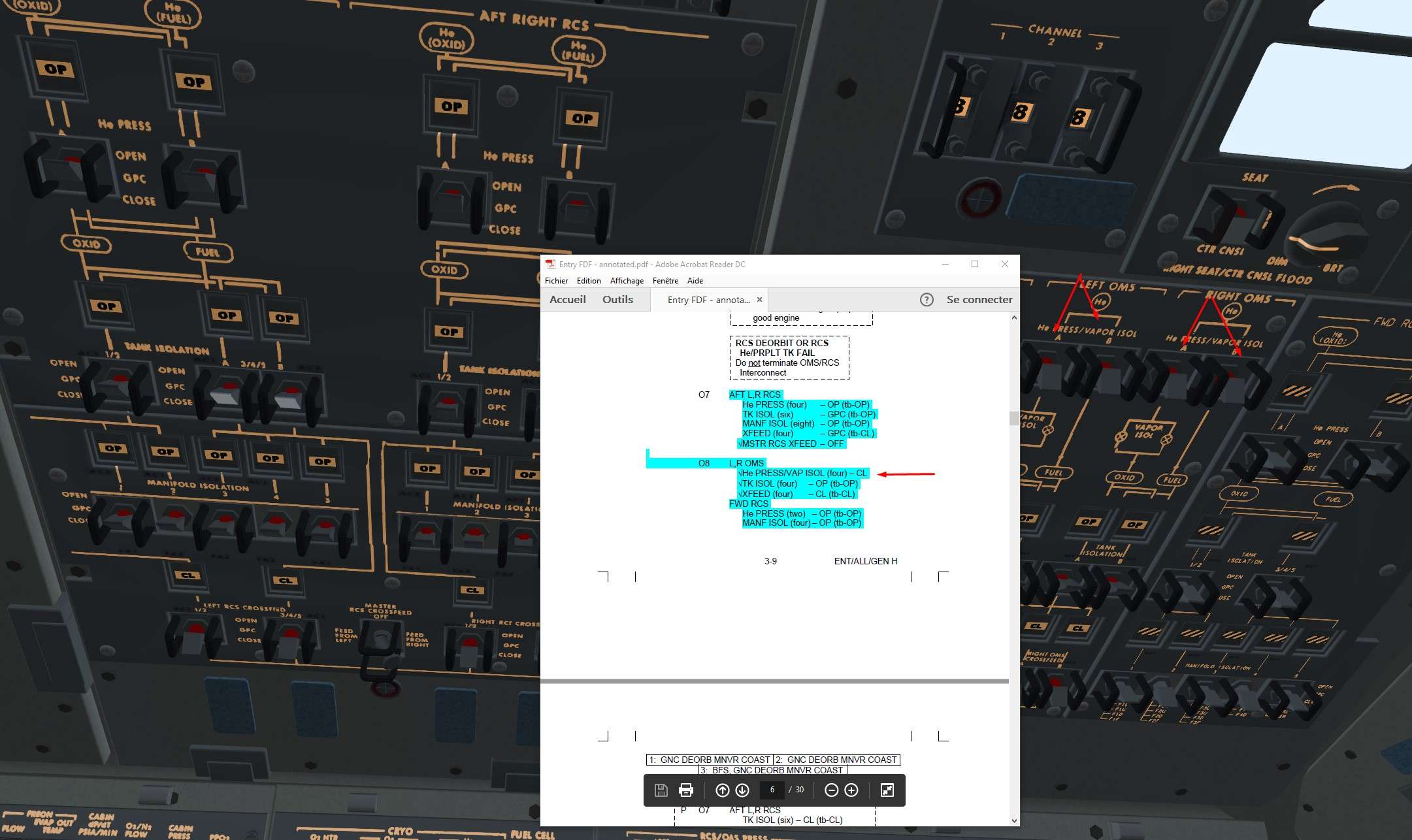
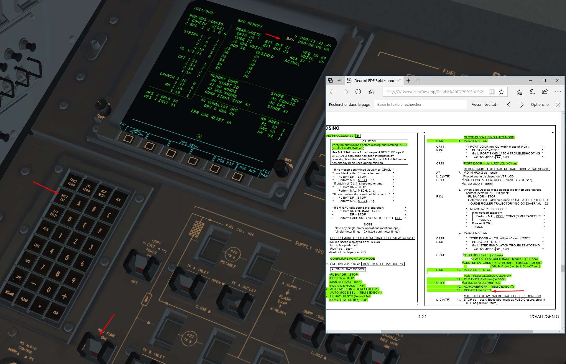
7)We configure the bay for Doors closing
We just need to activate payload bay Lights

Image


8)Let's close the doors
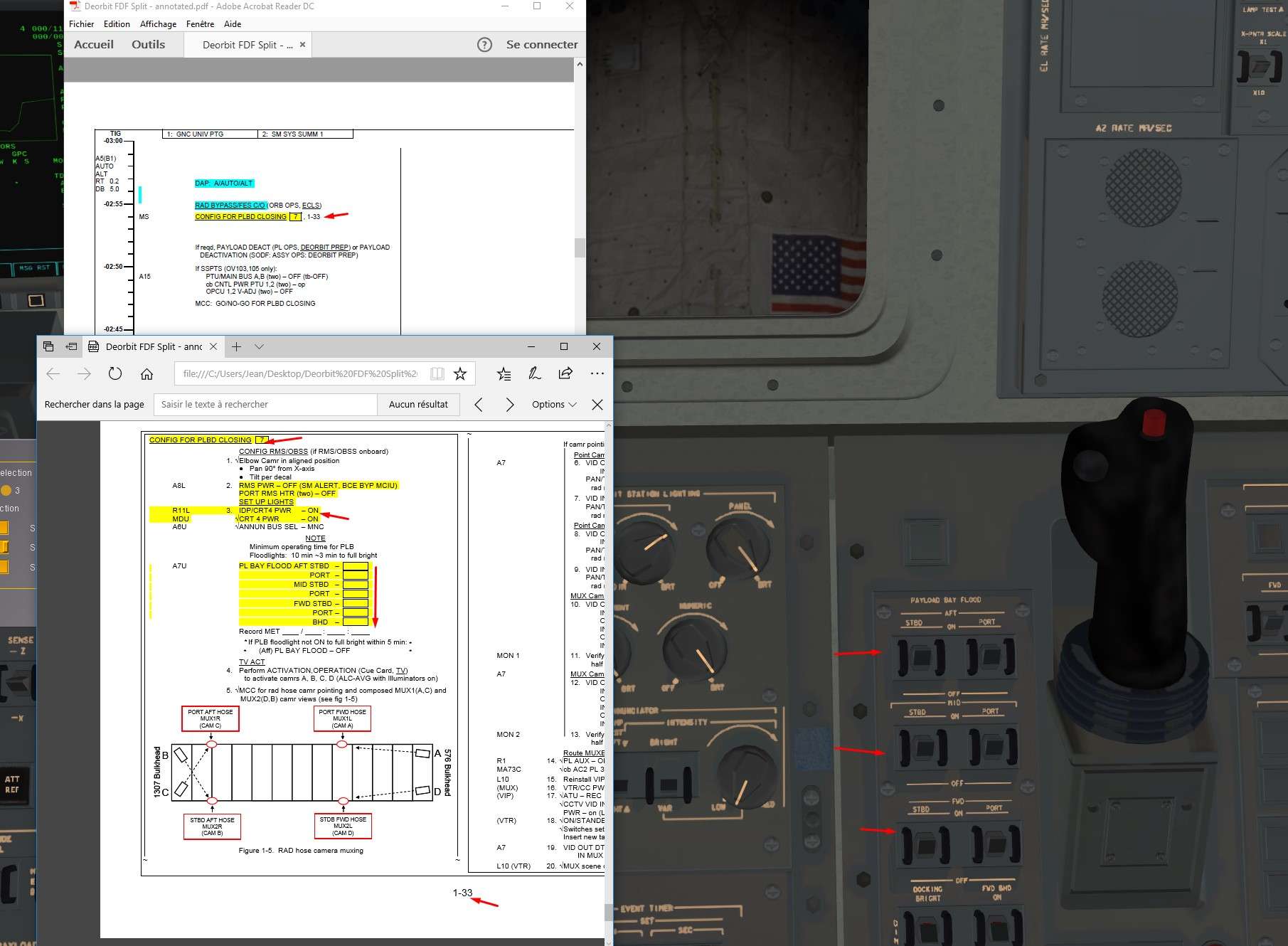
Several way to do it, Automatic, or Manual
We choose Auomatic, and it will be enough complex like that

We go in Major Function SM and OPS 202 to access the PL Bay doors display.
We check that the different parameters are coherent ( Doors opened, Latches position, no AC current,..)


Image


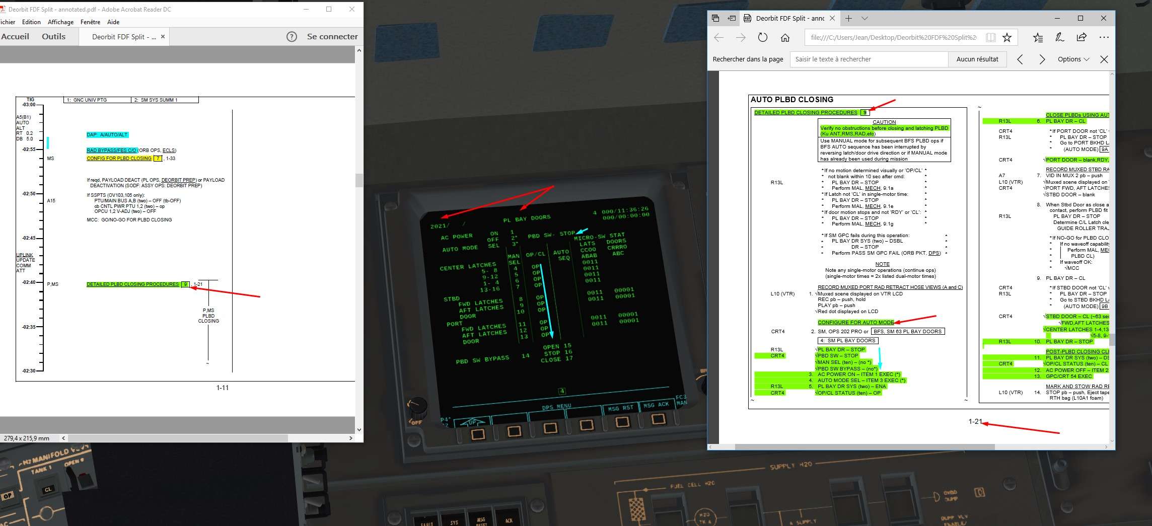
AC current and auto mode
Item1 and Item 3
Mechanical systems on and we close the doors

Image


Image


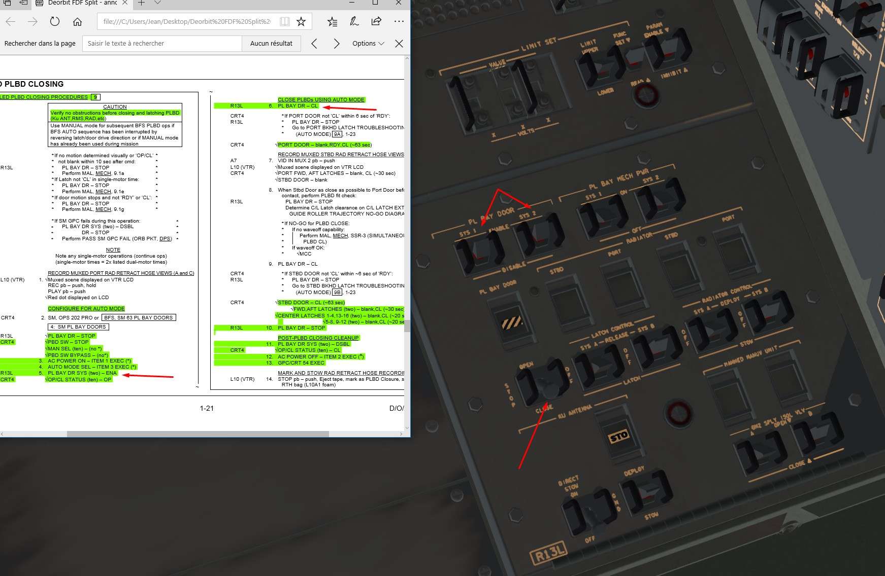
We monitor that everything is ok , and the sequence correct. First Port door and latches, then Starboard door and associated latches, finally latches between the two doors.

Image


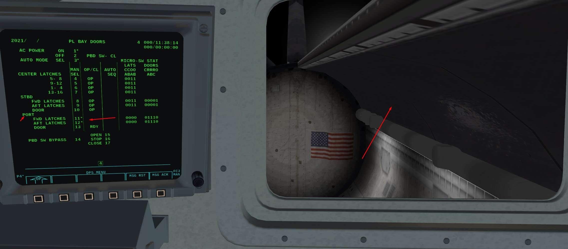
At the end, we should have that

Image


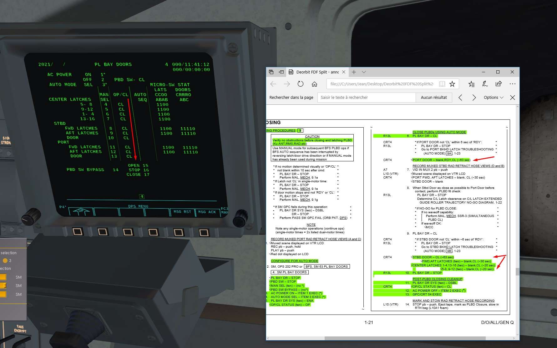
Mecganical systems off and AC current turned off Item 2

Image


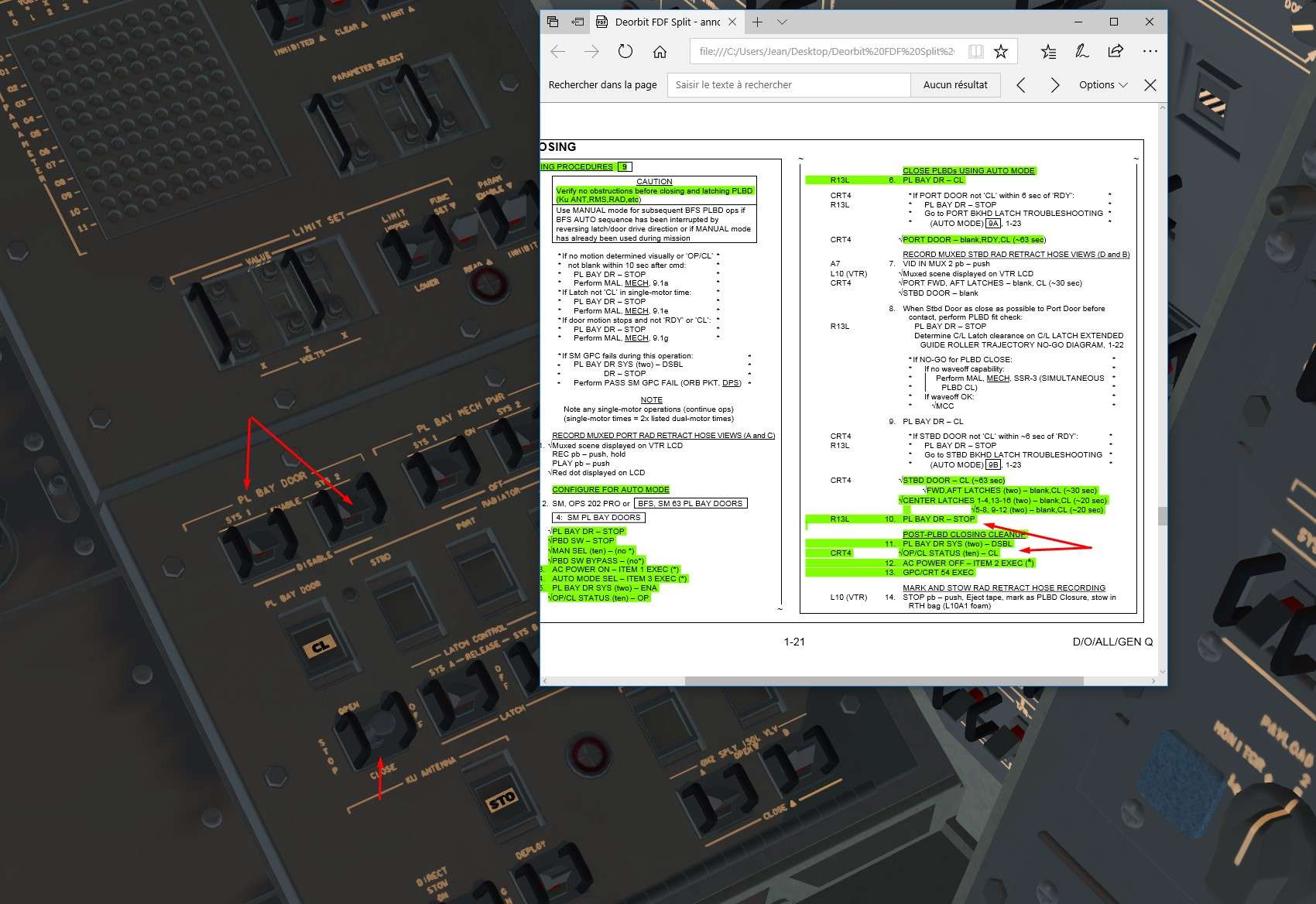
Finally, we linked the CRT 4 to GPC 5 GPC/CRT 54 and we turned it off

Image


With good use of time compression, we should be around 20 mn on Event Time at this stage

Image


9)Post doors closing actions
Pretty simple, we switch off the lights

Image


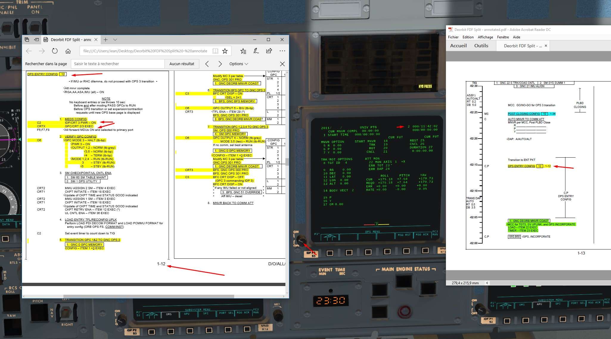
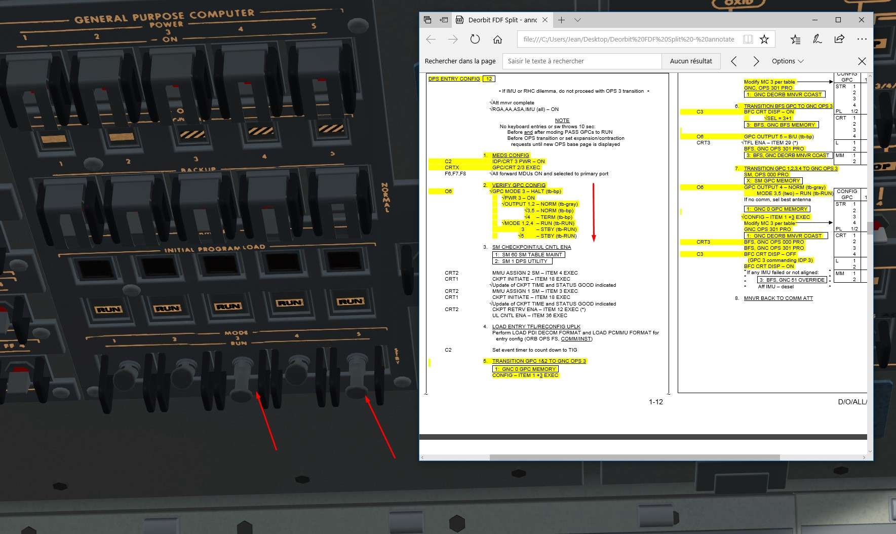
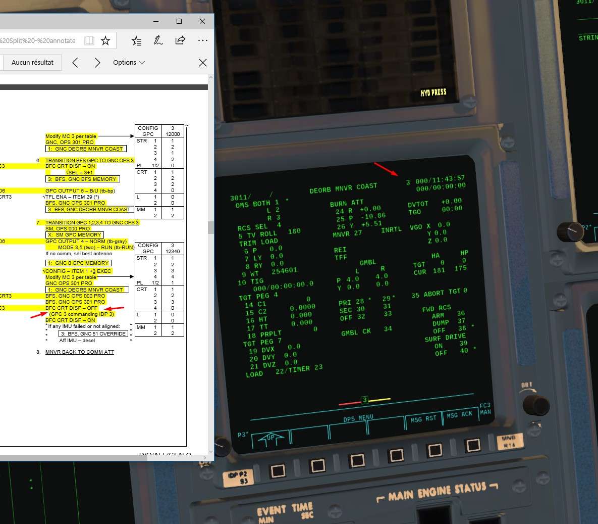
10)Time to configure the GPC for entry

In Simple GPC mode, we just have to transition towards OPS 3 by OPS 301 PRO to load the good NBAT for every GPC

In Advanced GPC, it's gonna be a bit more challenging


Optional part Advanced GPC transition towards OPS 3


It requires a bit of experience and reading about GPC, especially about their philosophy. It can be a bit overwhelming otherwise.

The goal here is to put GPC 1 to 4 in OPS 3 Entry Software with 2 Critical Bus on each ( redundance), and also to configure the independant BFS in OPS3.
GPC3 and 5 are sleeping, GPC 4 is doing the System Management and does not emit on Critical Bus.
Hence, we will have to proceed step by step as we have differents GPC in differents Mode and Major Function to put back together in OPS 3

First GPC 1 and 2 in OPS3. Then BFS in OPS3. Then GPC4 out of SM. Waking up of GPC 3. Finally, we will link GPC 1 to 4 together in a Redundant Set in OPS3.


We turn on CRT 3 and we assign it a GPC GPC/CRT 23

Image


We check on O6 panel the good position of switches
GPC 3 and 5 are put back to work by moding them in STBY mode first

Image


We configure the G3 NBAT ( Bus assignement for OPS 3 entry software) in order to switch GPC 1 and 2 in OPS3
Don't forget item 4+0 item 5+0 to avoid that GPC 3 or 4 are loaded with OPS 3 too early

Image


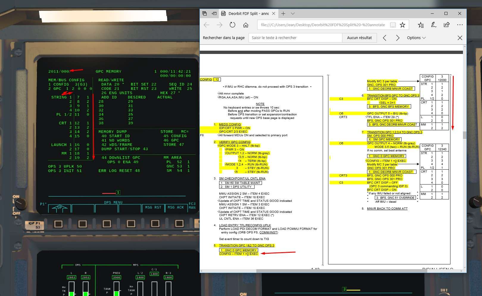
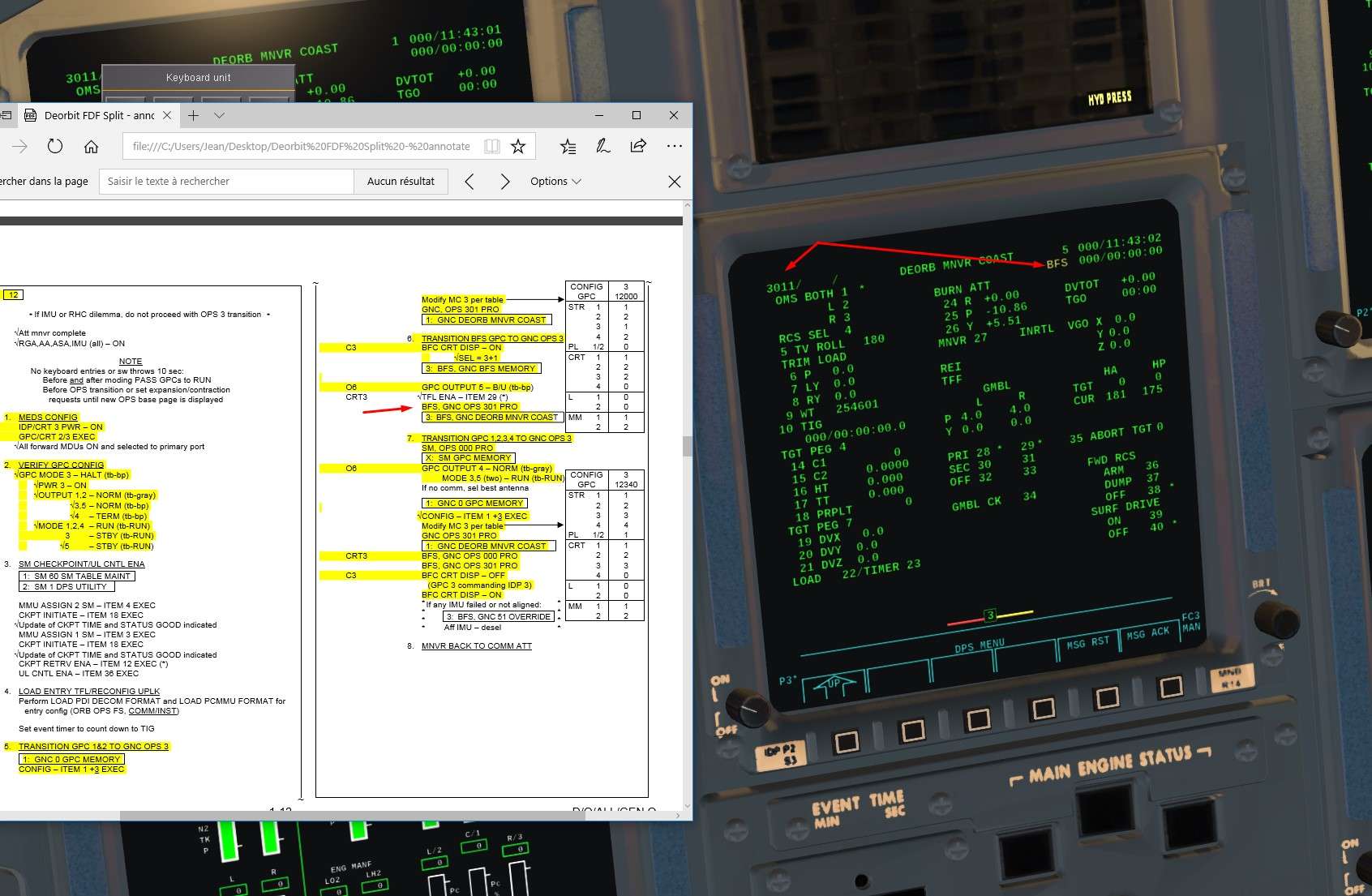
We transition to OPS 3 OPS 301 PRO

Image


Time for the BFS now, like before, we display it on CRT 3

Image


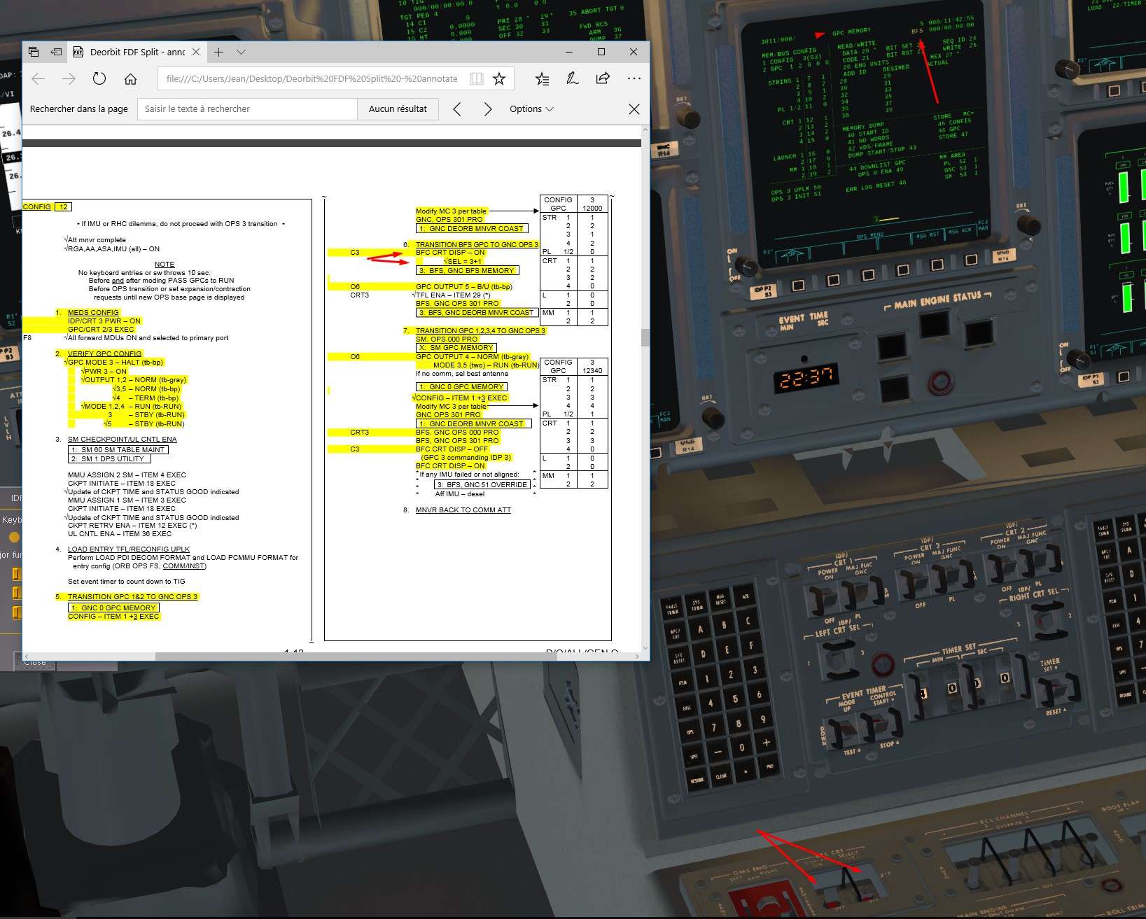
Then we load the OPS 3 into the BFS with OPS 301 PRO on CRT 3


Image


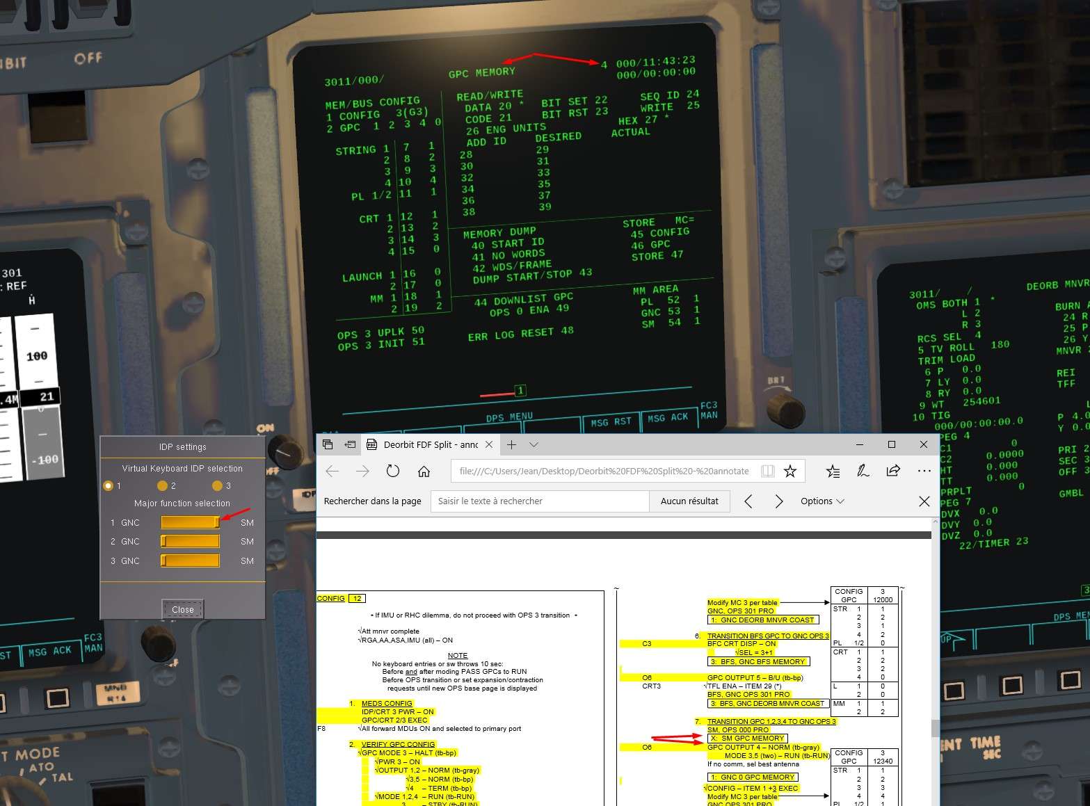
We stop the SM Function within the GPC 4
For that, we display the GPC 4 on a CRT ( 1 here) GPC/CRT 14 EXEC and we switch to System Software mode only OPS 0 PRO

Image


We put back GPC 4 to normal Output to allow it to emit on Flight critical Bus
GPC 3 and 5 are put back to RUN mode ( STBY previously)

Image


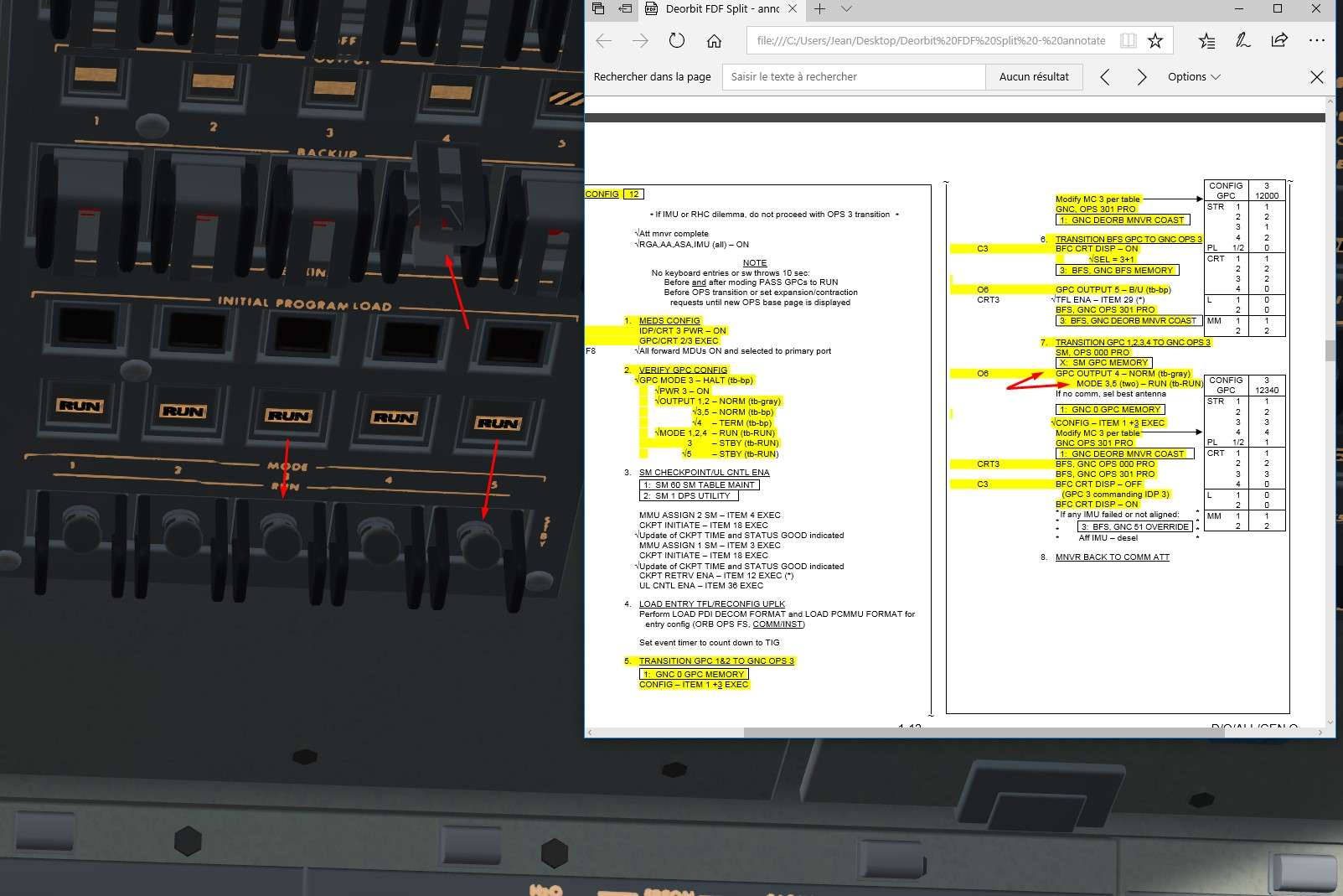
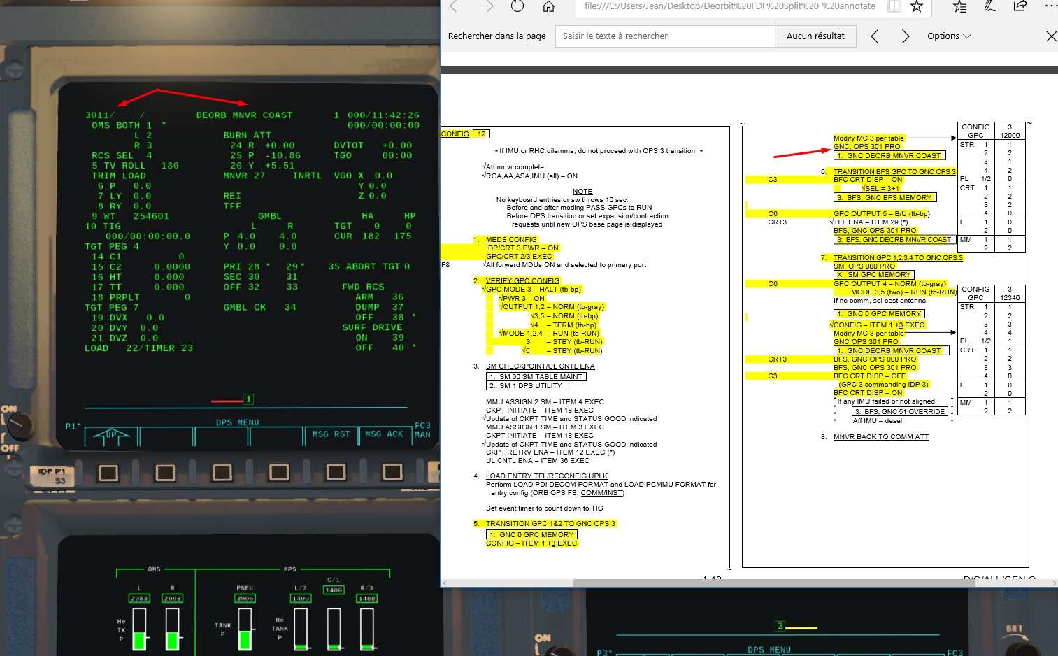
We reconfigure the NBAT G 3 like before, but that time we include GPC 3 and 4
Don't forget item 4+3 item 5+4, if not only GPC 1 and 2 will be in the redundant OPS 3 set.

Image


And finally OPS301PRO to load the new NBAT and put GPC 3 and 4 in OPS 3 with their friends GPC 1 and 2

Image


We recycle once the BFC Display Switch in Off position to check that the CRT 3 is well commanded by the GPC 3 when BFS is not diplayed on CRT 3
Then we put back the display switch to On to have th BFS on CRT 3 for the reminder of the mission

Image


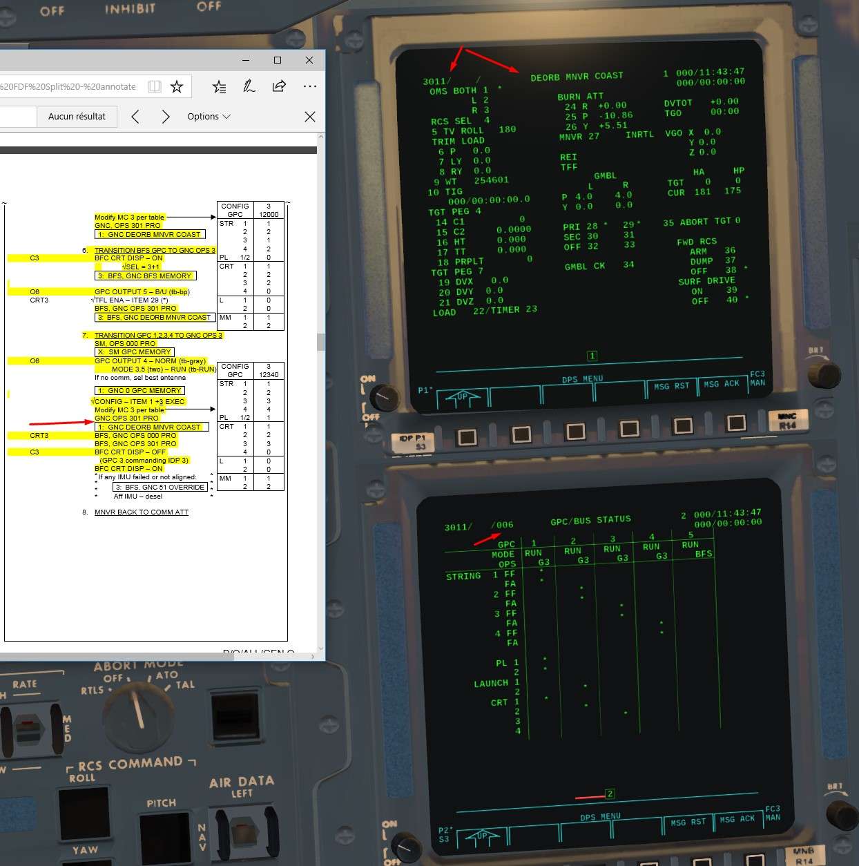
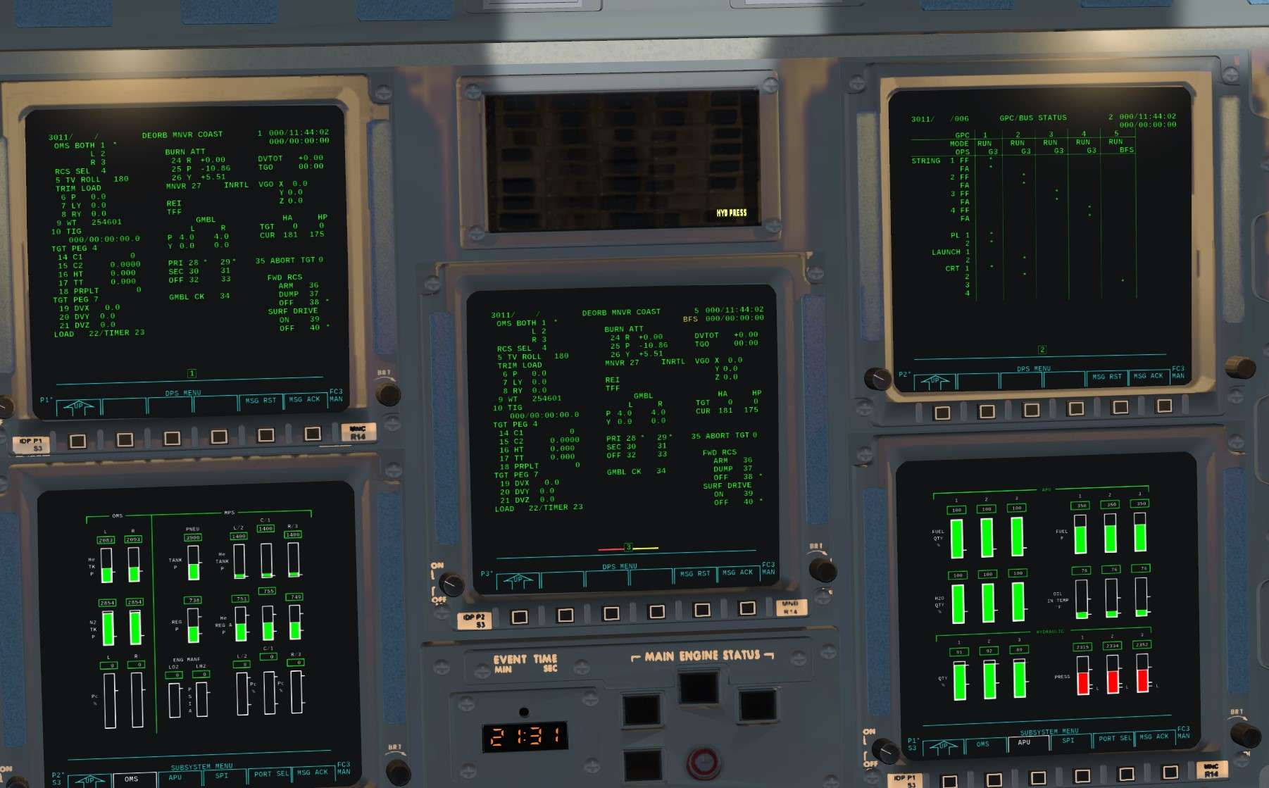
Here the global result we should have
GPC 5 on CRT 3
And on SPEC 6 ( CRT 2), we can check that GPC 1 to 4 emit on 2 Critical Bus each, CRT 1 and 2 are commanded by a GPC ( 4 is off)
Perfect, Awsome level of fidelity to real stuff here


Image


End of optional part


Let's continue


11)We are now going to calculate the Deorbit Burn Solution

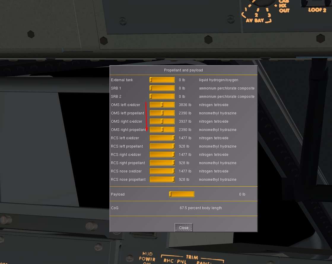
First of all, Center of Gravity matter ( COG)
We start the mission with OMS fully filled with propellant, and we will use around 30 to 40 % of it maw during the burn
We will have too much remaining, hence Afterward COG and Stability problems during entry.
2 solutions: Either we incorporate an out of plane component ( y LVLH axis) during the burn ( at least 400 ft/s) to eliminate propellant without affecting shape of the orbit. Or we edit the quantity of OMS propellant in the menu for that ( picture below)


Image


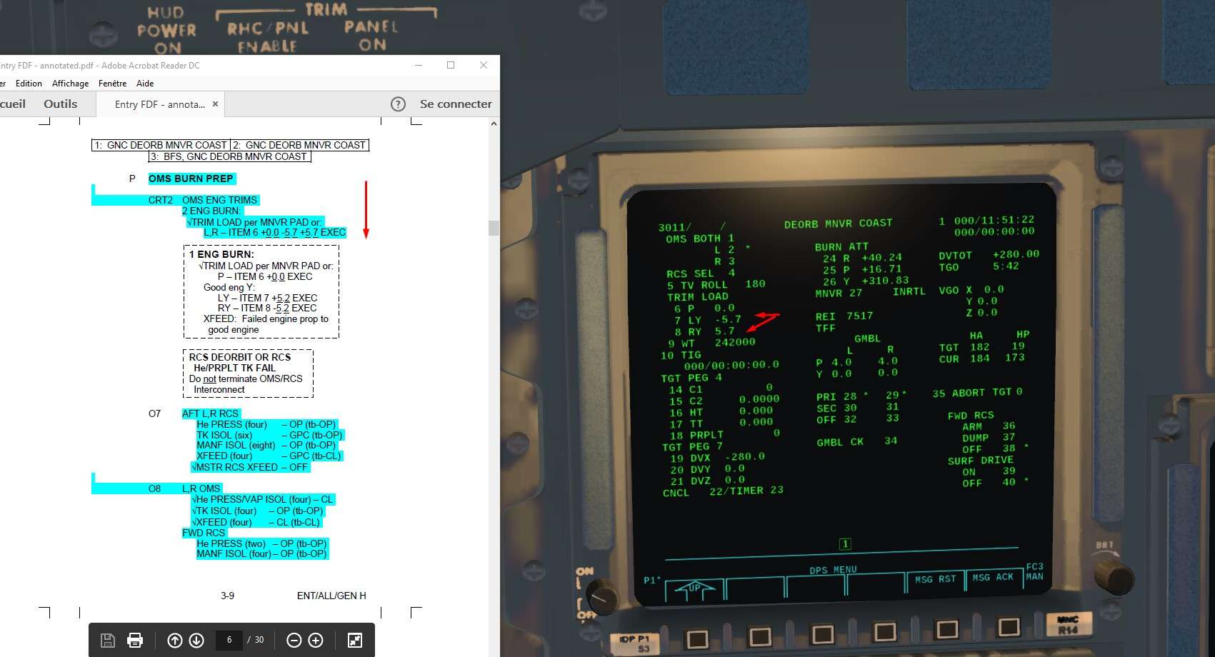
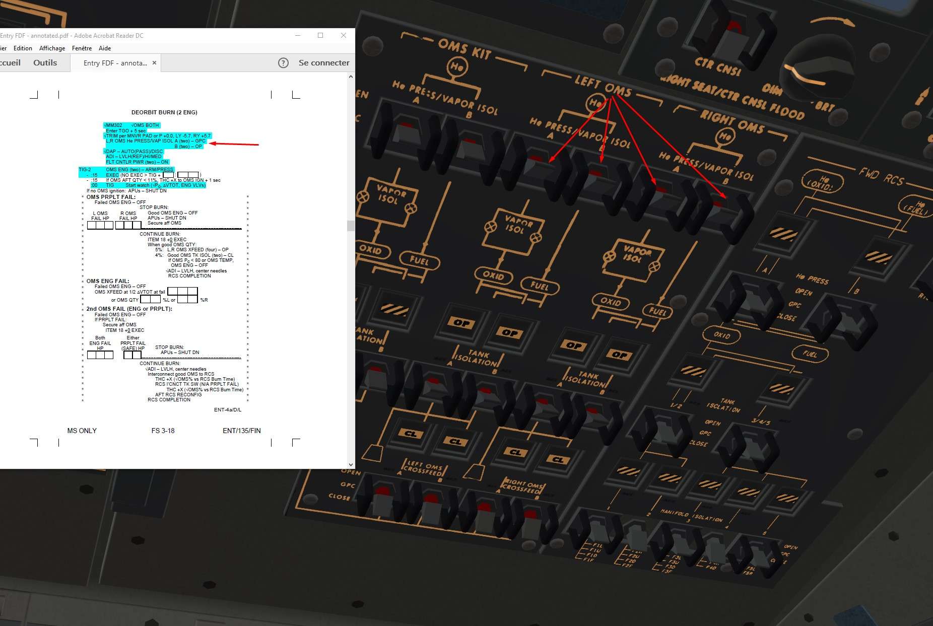
We gonna load initial parameters : Trim and gross weight of the Orbiter
For the trim, ITEM 7 -5.7+5.7 It allows the nozzles to align parallel with Shuttle X axis going through the CoG for a 2 engines burn.
With no trim, Nozzles are not naturally align with that axis but offset by 6 ° outward in case of a single engine burn, where the engine will have to push through the Cog and not parallel (hence with a sideslip angle).

ERRATUM: For the rest of the screens until the burn, you can see a Star (*) right of L2 parameter. It indicates that I wrongly choose a single engine ( left one ) burn. My mistake here.
It is totally feasable, but duration of the burn and trim have to be different.
I saw that too late ( during the burn, just one engine ignited and I saw that mistake) So, I did again all the prep and a two engine burn, but didn't do again the screens.

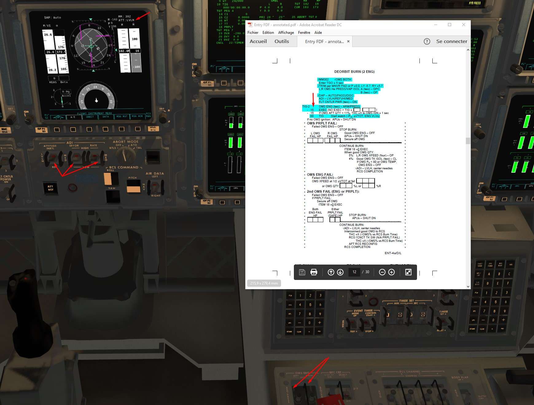
Disregard that mistake, we will do a two engines burn, and the star (*) should be right to item [b]OMS BOTH 1 * and burn time TGO should be halved, around 3 mn
[/b]


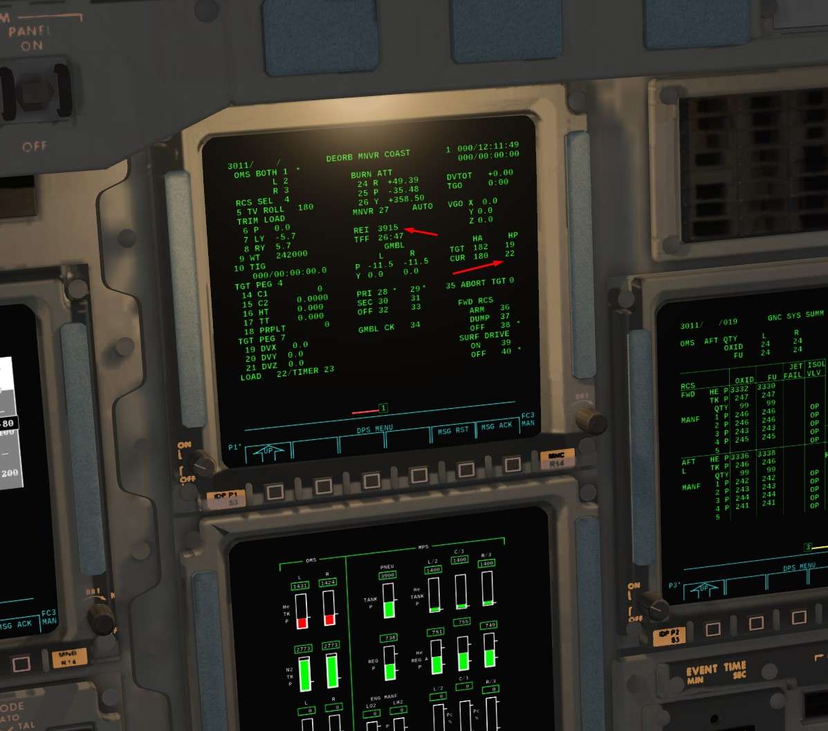
Orbiter weight also changed as we dumped fuel in OMS tanks, so have to ask MCC the new one and correct it in the computer.
Item 9 + 242000


Image


What is the intensity of the burn?

We have a Perigee at 175 Nm and we want to decrease it above KSC around 20 Nm, reminder of the rule of thumb 2ft/s for 1 Nm of height
We have to loose 155 Nm of height, so around 310 ft/s of speed to loose.
We affinate that and take Vx= -280 ft/s ( Negative speed on X LVLH axis because we want to do a retrograd burn, we have a quasi circular Orbit, so X LVLH axis is almost the same than the Velocity Vector one, hence the burn on X axis only and no Z component)
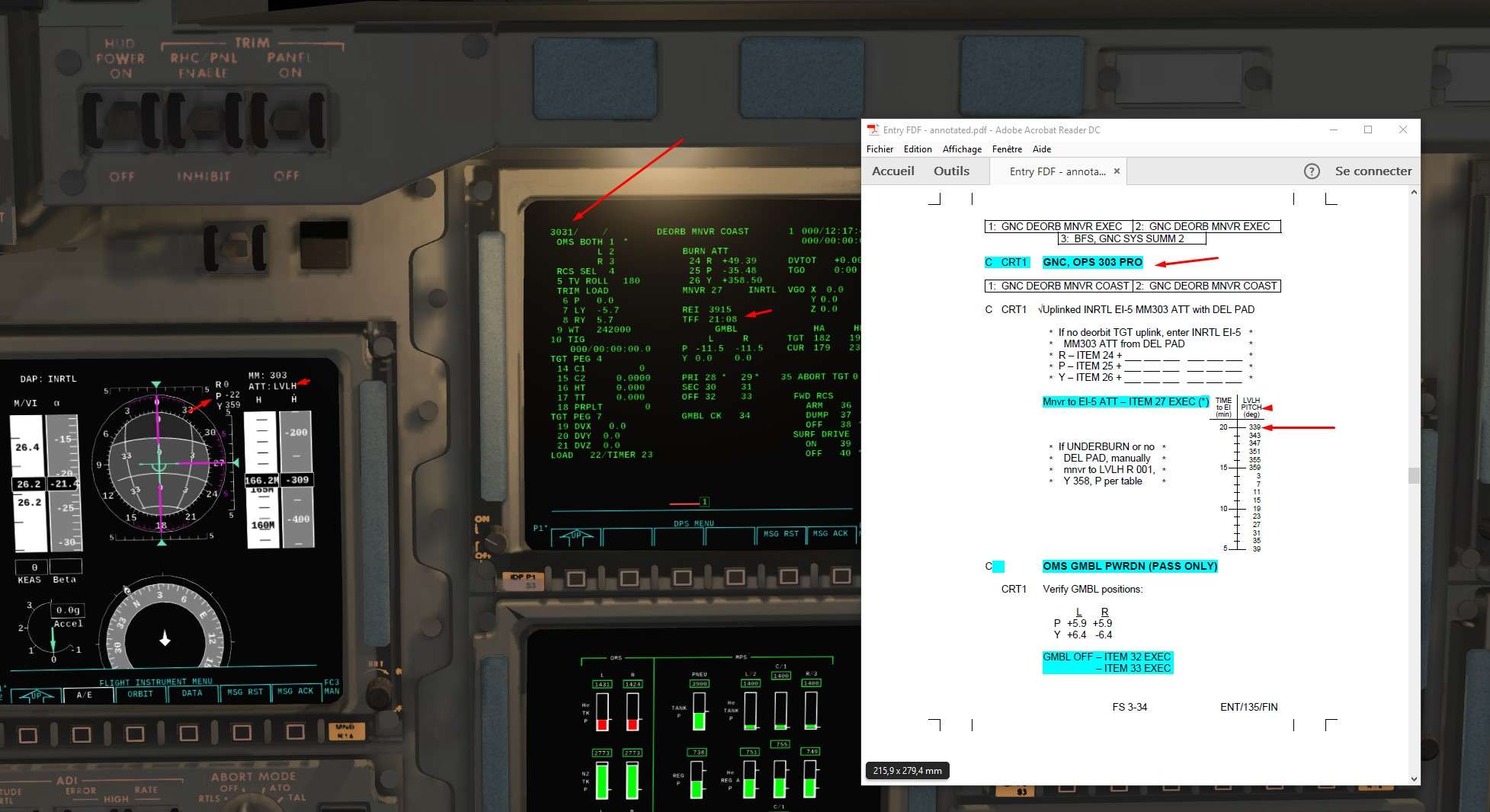
Height of Perigee (HP) in Target (TGT) is 22 Nm, close enough.

Item 19 - 280
Item 22 to load


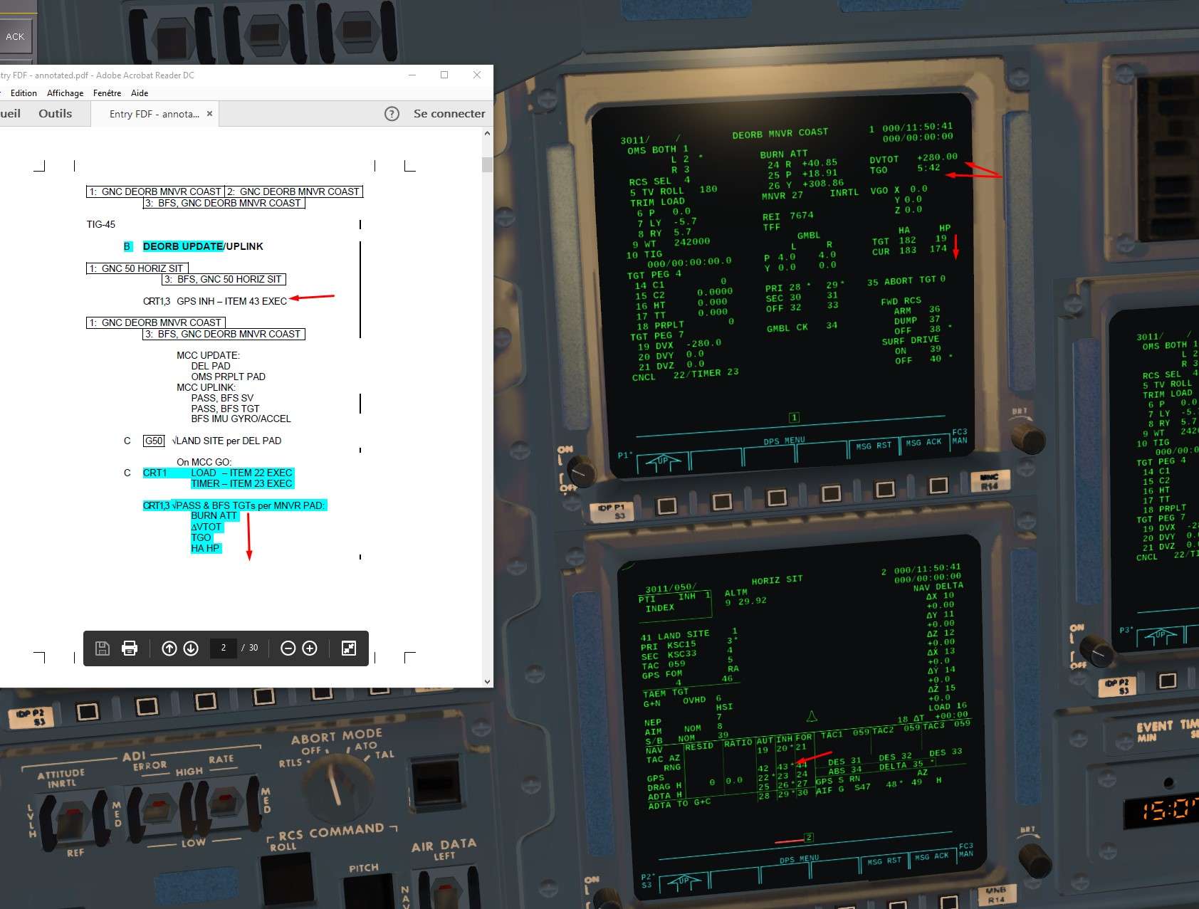
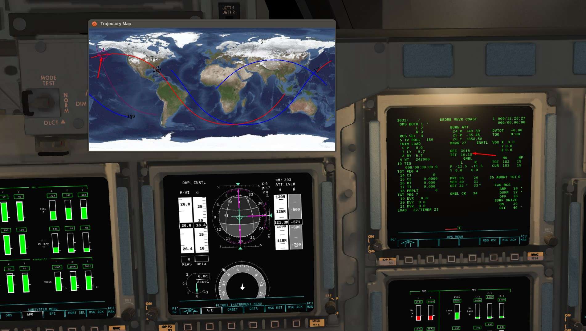
We can see that REI appears, very important value to know when we have to perform the burn
Rentry Interface Range, or the distance between Entry Interface ( 400 kfeet) and landing site ( KSC)
We saw earlier that we wanted to have REI around 4000Nm to have a good angle of entry, not too flat, not too steep. So when REI value approach 4000 Nm, we will press EXEC on the keyboard to perform the burn.


Image


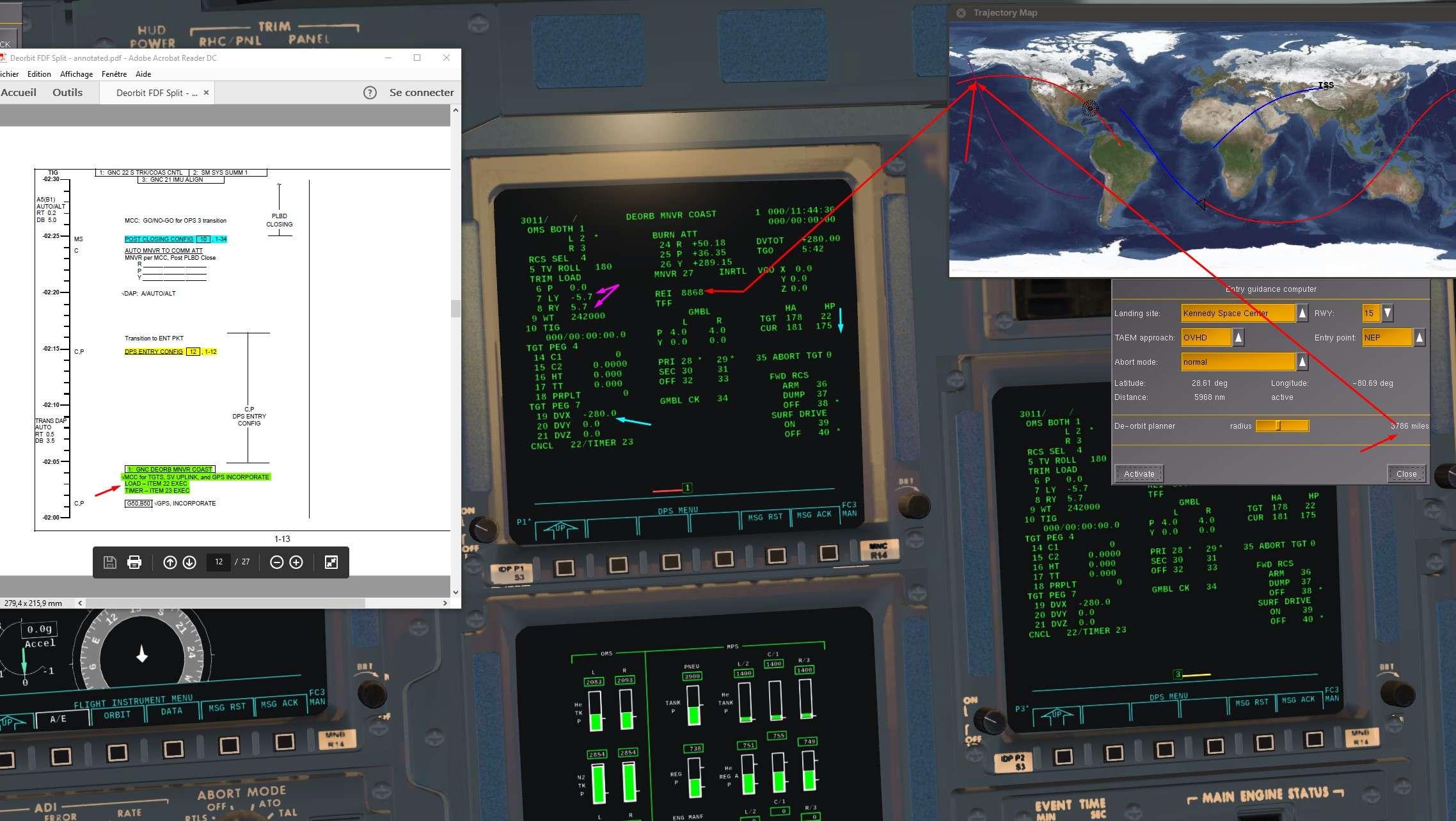
It works well like that.
In real life, MCC would upload a burn solution based on different variables ( linear equation linking horizontal and vertical velocity wanted at EI, angle Theta between burn and EI interface, and height HT wanted at EI so 400000 feet) You can see those parameters below TGT PEG 4, not implemented yet.
Outcome would be the same, just a different way, more efficient and safe (closed loop guidance) for Deorbit burn in Real ( critical burn)


12) We shut down the Star Trackers
Spec 22 Pro Item 9 and item 10

ST Software on Idle first

Image


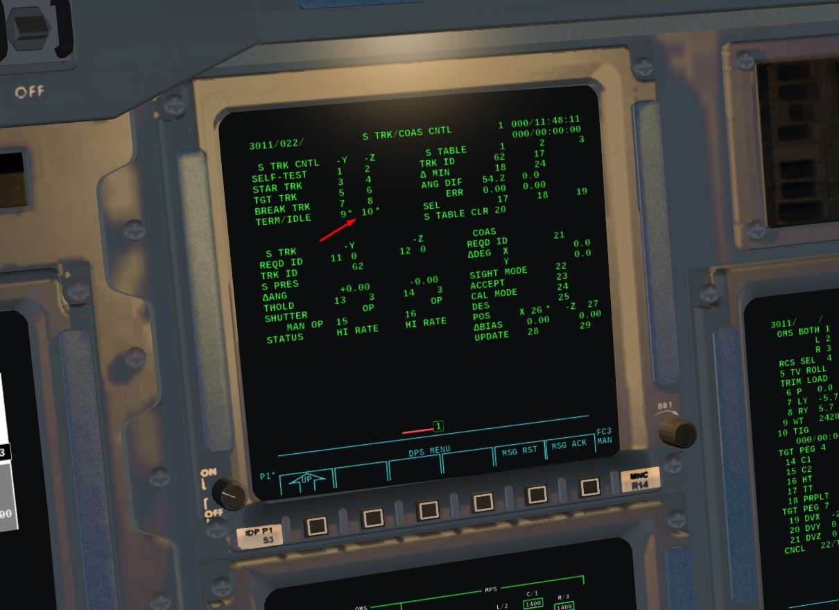
Now, Mechanical shut down of the ST

Image


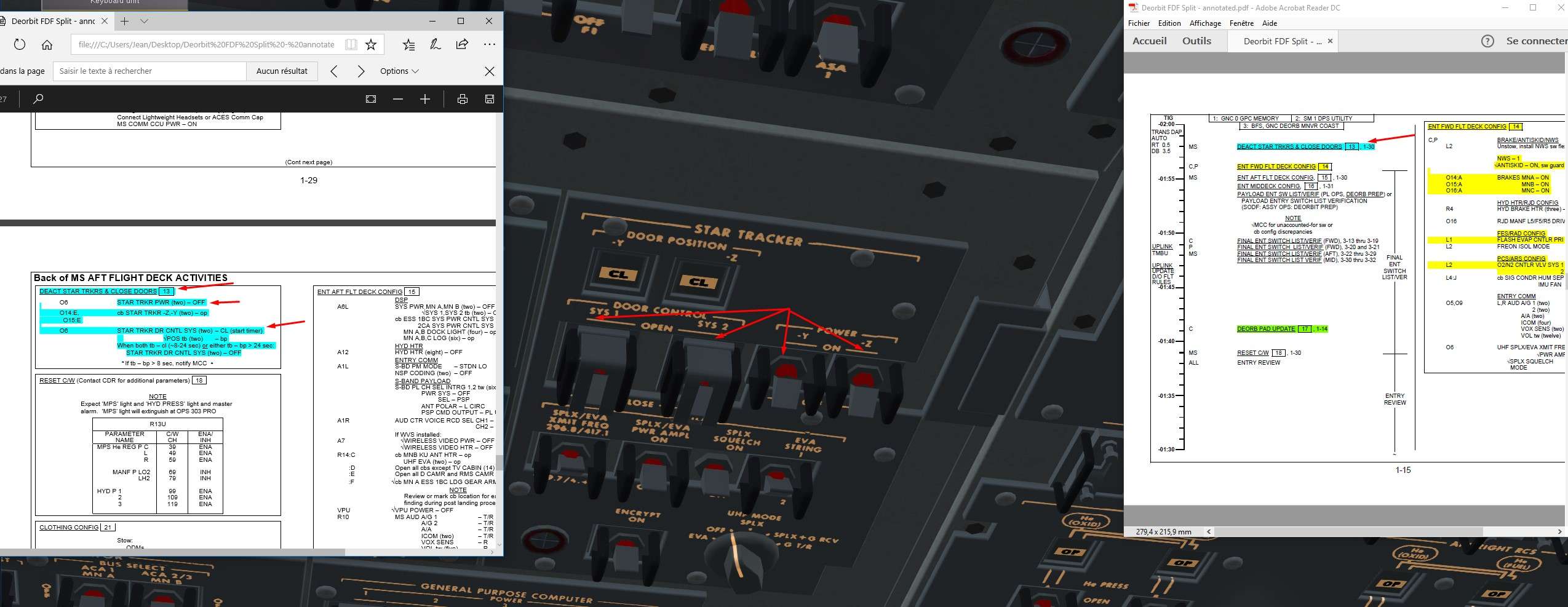
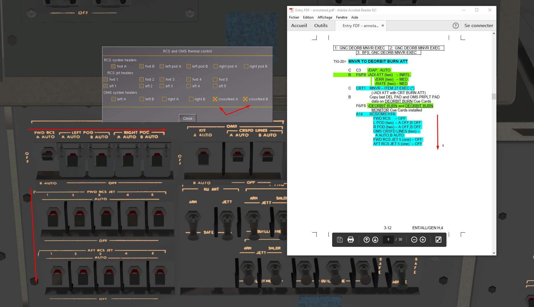
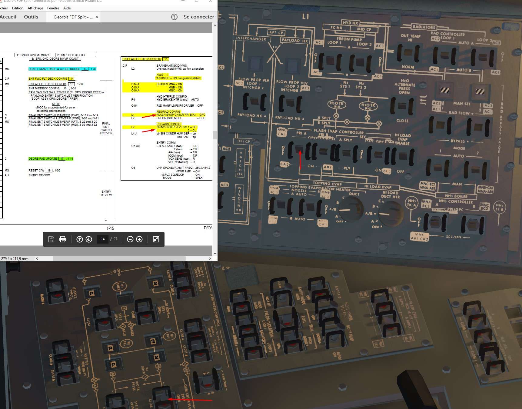
13)We finalize entry cockpit configuration.
FES on GPC to allow Computers to control the FES during entry. Also, small changes in Pressurisation Control System to be fed by system 1.


Image


Optionnal

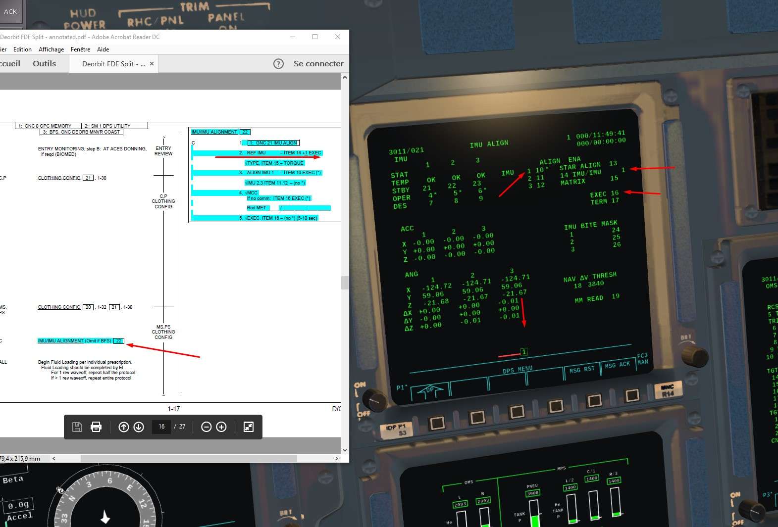
14)We can do an IMU alignement before the entry. At this stage, it is a IMU /IMU alignment ( one IMU as a reference) Star Trackers are off, so Stars are not available to serve as a reference to align the IMU.
Spec 21 pro to go on IMU display page.
I am not writing too much about it, I will detail that longer in a specific part ( a lot has to be say about IMU capabilities :) )

Image


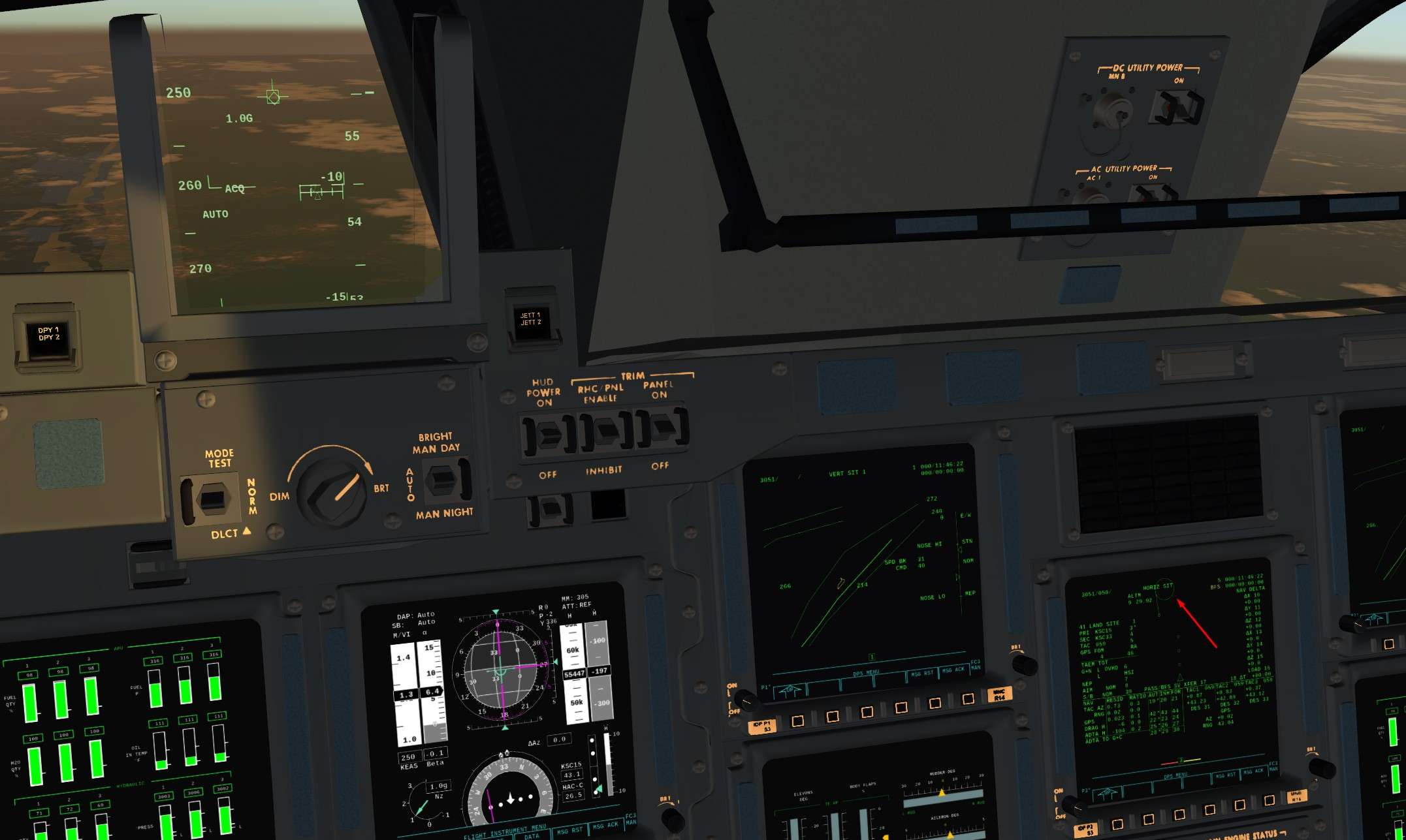
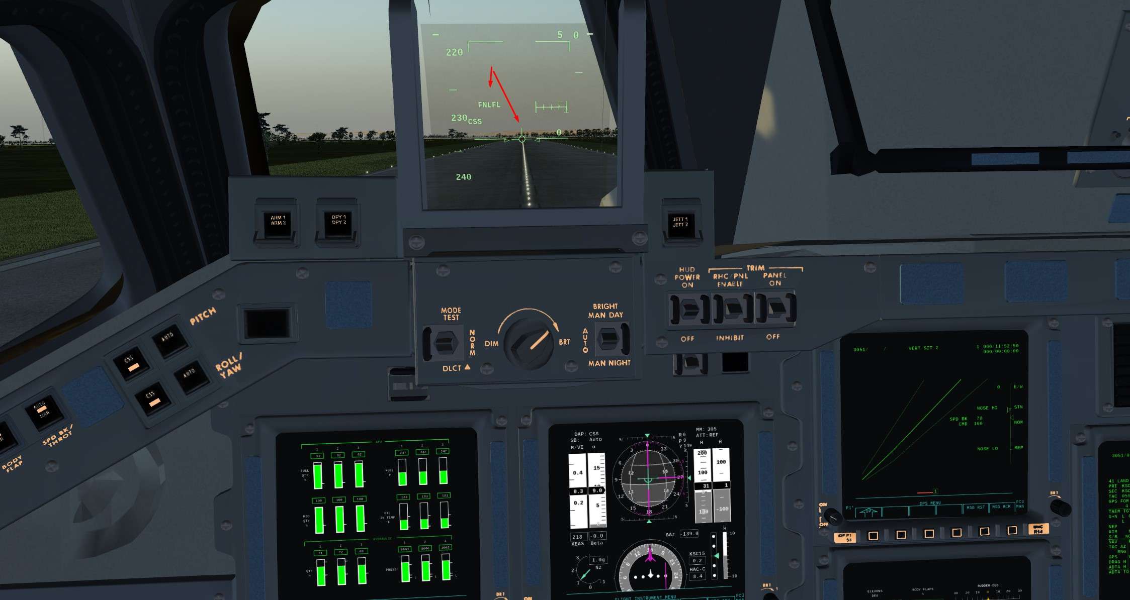
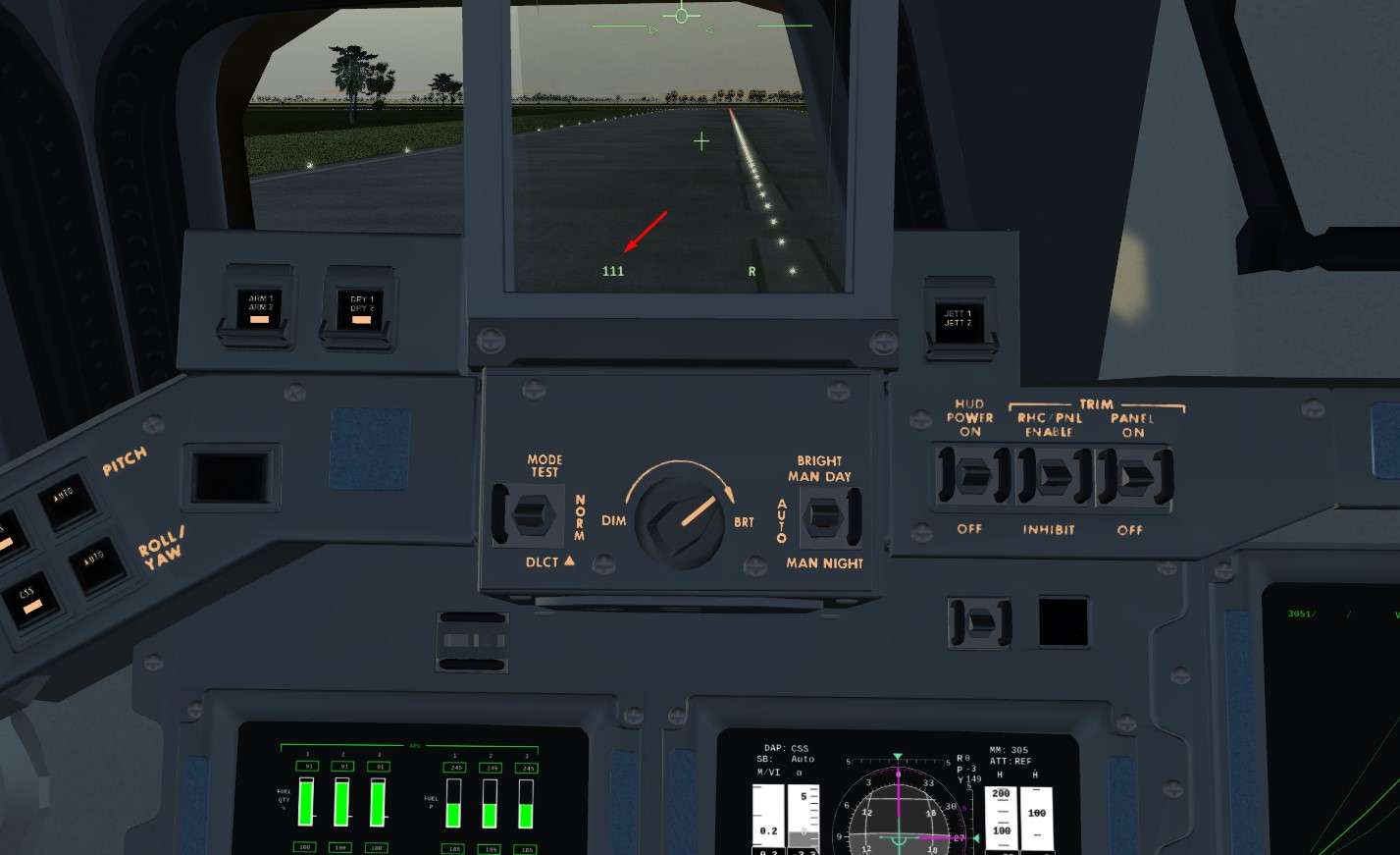
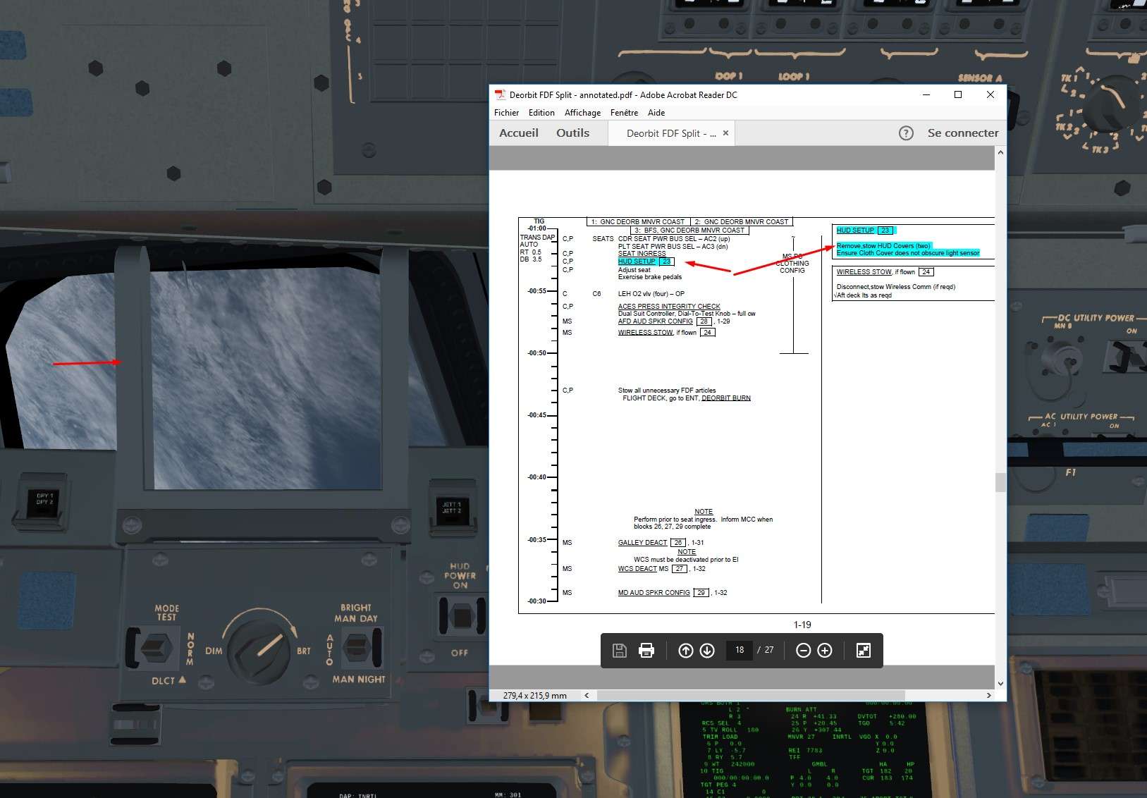
15) Final Step, we remove the HUD cover ( click on grey part)
The level of details

Image


And a cross check of all what we did with the In Game checks

Image
Last edited by GinGin on Sun Oct 29, 2017 9:50 pm, edited 1 time in total.
GinGin
 
Posts: 1580
Joined: Wed Jul 05, 2017 11:41 am
Location: Paris
Callsign: Gingin

Re: Space Shuttle Tutorial Full Entry: From Heaven to Ground

Postby GinGin » Sun Oct 29, 2017 9:08 pm

II) Deorbit Burn and Entry Preparation


We gonna use now the Entry Checklist which starts in real 45 mn before the burn ( 15 mn in our situation)
We are nicely catching the time with good use of time compression


1)We check once again the burn solution : Velocity, inertial attitude BURN ATT, length of the burn TGO and total velocity DVTOT.
Also, check the target Apogee and Perigee ( TGT HA HP)
As there is still a mistake from my part here, TGO is 5:42 instead of 3 mn ish with 2 engines burn.

Image


2) We check that nozzles can move freely ( Gimbal)
Item 34 A star * appears right of GMBL CK and disappears once the check is completed.

Image


3)APU Pre Start
Mainly check to do.
Hyd Pump on Low, Apu controller On et Boiler N2 Supply On ( Nitrogene pressurising Water Tanks that will cool down Hydro and Oil from APU gearbox)

Image


4) We check on Spec 50 the good datas and configuration for final entry phase ( TAEM).
Good runway here is KSC 15.
Normally, nothing to change, just some checks.

Image


5)One more step to verify burn solution ( and I still didn't notice the 1 engine burn only ahah )

Image


6)We check that the RCS:OMS valves are in correct position
Here, we just have to close the OMS He Press/vapor isol
It allows to isolate the propellant tanks from the Helium tank that pressurises them during a burn. We avoid like that to loose all the Helium in case of leak in the pipes between two OMS burn.
No Helium, no burn ( Pressure feed combustion chamber)

Image


7)We close the ventilation doors ( 10 around the Orbiter, linking non pressurized part of the Orbiter to the exterior pressure condition)
Item 44

Image


We transition to OPS 302 PRO, similar page than previous one used for the Deorbit Burn.
Burn solution is saved during the transition hopefully.


8)We will now put the Orbiter into the correct Inertial attitude for the burn.
DAP Auto mode and ITEM 27
It will put the Orbiter in a good burn attitude and update that one until we perform the burn.


Image


9)Reconfiguration of RCS/OMS heaters ( all Off exept crossfeed lines)

Image


10)5 mn before the burn, we start one APU.
Aim is to have at least one APU working after the burn in case of malfunction of the two others.
Being without Hydraulical power for Entry is not an option, and would lead to a crash for sure. So better to be sure to have a working APU before to decrease the Perigee :)

Image


11)OMS valves reconfiguration before the burn, Helium is now feeding both propellant tanks in each OMS system

Image


Last verification of front switch ( Frame in LVLH, Medium error and rate for monitoring)
OMS Eng checked on ARM/PRESS, if not, no Nitrogen to open bi-valves that separate propellant from combustion chamber.

Image


Next screen will show normal behavior on 2 engines ( I corrected the small mistake )and we have 3 mn of burn TGO. Good.
REI is around 4000 Nm, so we press EXEC and monitor the burn.

Monitoring of : Valves well opened at 100% and Pc combustion full white and above 80 %
Also, we can check the ENG IN P ( Engine inlet pressure) that indicates the pressure of either the fuel or oxydant before the combustion chamber
Value should be lower than the on in respective tanks due to propellant suction into the chamber.
That is an important parameter to detect an egnine failure.

For example, if the ENG IN P of the oxydizer is high and the Pc parameter is below 80 % , we can deduce that something is blocking the Oxydizer after the engine inlet line.
Hence, that engine is lot, but we can still use the remaining fuel to do a cross feed and fisnish the burn on one engine.
Same stuff with ENG IN P Ox low that time, we can deduce that there is a leak somewhere between the Oxydizer tank and the main chamber, so both the engine and remaining propellant is lost.


Image


Visually

Image


Burn is over , we check the results ( REI, HA and HP)
REI of 3900nm , and HP of 22 Nm, perfect and in accordance with the map ( cercle indicates the estimated EI, it will move a bit before stabilizing)
.


Image


Image


12)Final reconfigruation of OMS, Helium valves are closed once for good

Image


We switch in OPS 303 PRO, Coasting phase between Deorbit Burn and Entry software OPS 304
We go in the correct attitude for entry.
Autopilot will maintain an inertial attitude, and we want to be in 20 mn in LVLH frame at: Pitch of 40 °, no yaw or roll at Entry Interface.
So a Pitch attitude of 330 ° ( -30° in the game) should bring us at an attitude of 40 ° in 20 mn of inertial attitude.

Image


Event Time set to time before EI interface ( TFF), 20 mn in our case

Image


13) OMS gimbal are switch off, no more move OMS

Image


14)We gonna dump to remaining propellant in Forward RCS tank
We want to avoid potential hazard during entry.
More over, only the aft RCS are used during entry for shuttle control.

Image


4 RCS at the front fire at the same time to avoid any roll, smart way to dump, no?

Image


15)Check that the switches linked to navigation and monitoring for entry are in the good position

Image


Image


16) 13 mn before entry, we start the remaining APU ( 2 and 3)
Fuel tank opened and Starter On

Image


17)Pressurization of the SSME with hydraulic liquid to allow their repositioning of the nozzles for Drag chute opening
Crazy no :)

Hyd Pumps switch on Norm ( 3000 PSI)

Image


Checklist in game to verify that everything was done

Image


Voila, Rendez vous 5 mn before the Entry Interface for the final Countdown


III)Entry of the Beast


Entry coverage will be a bit more lighter, cover in depth here : http://wiki.flightgear.org/Flying_the_Shuttle_-_Entry


1)5 mn before EI, we switch to OPS 304, ideal trajectory appears and we check that we are in Auto for Pitch and Yaw/Roll
It is better to be a bit low than way to high. Between Mach 25 and 17, if we are too high, we will be close to thermal limit, which is of course a hard boundaries and lethal one.

Image


2) EI reached, 400 kfeet and 3700 Nm, all good.

Image


A bit low on trajectory, AP will limit the bank roll to not dive too fast into the atmosphere and keep us a bit longer on minimum Drag/Lift equilibrium trajectory

Image


West Coast in sight

Image


3) When Drag reaches 10 ft/ss ( Drag is measured like an accleration), we check the implementation of DragH in Spec 50.
It is a model allowing to calculate the present altitude with the present drag experienced by the Shuttle and IMU. Important filter to update the State vector (SV)

Image


4) Mach 19 , We check that the Hyd valves of the SSME are closed.

Image


5) Mach 15 , final check that navaids are well configured

Image


We are back on the nominal trajectory, perfect

Image


And a beautiful Sunrise for our coming home

Image


6)Mach 12 , we put back on line the radiators to allow additional cooling ( 15 mn) with the cold Freon trapped during the Cold Soak Procedure.
Rising Exterior pressure does not allow a good ejection anymore of the hot vapor water present in FES into atmosphere


Image


7)We incorporate now the TACAN into navigation filters to update the SV
In RESID, you can see the difference between measured distance between IMU and TACAN station, and measured distance between TACAN receiver and TACAN station.
Here, value is 1.05, so 1 Nm of difference between real position and estimated position of the Shuttle calculated by the IMU.

ITEM 19

Image


8)Mach 5 , Probes ( ADTA) deployed

Image


9)Spec 51 to verify that data from probes are correct. We compare them to those present on the Primary Flight Display (PFD) fed so far by the IMU

Image


If datas are good, we don't delay their incorportation ( before Mach 2)
Item 25 and 28
PFD will be now driven by ADTA, and altitude calculated by Probes will replace the one derived from DragH model for navigation filters.

Image


10) Finally, at Mach 3, we switch On the HUD and check that the APU are working well. ( Fuel remaining, good behavior of water boilers that cool down APU oil and Hydraulic liquid)

Image


Almost there, ready for the last 5 mn of pure adrenalin??


IV) Terminal Area Energy Management (TAEM) and Landing


Same than before, lighter part, full TAEM tuto here: http://wiki.flightgear.org/Flying_the_Shuttle_-_Final_Approach


Well, we are now at Mach 2, just below 100000 feet, runway in sight, and some distance to glide with a brick
By two times, by taking screens and piloting like a cow I crashed the Shuttle into the Swamps

So, I restarted directly the scenario at TAEM Phase. I arrived by the South instead of the East with our scenario. No big issues here, steps will be the same.

Image


1)We are in OPS 305 ( Vert Sit 1 then 2), 80000 feet to dive into without exceeding 330 kts

Image


Mach 1, we check flight controls and we take the beast in manual ( CSS en Pitch et Yaw/Roll)

Image


2)Closing to the HAC, big 180 ° to perform to be align with the runway at 7 Nm at 12000 feet

Image


3) Becoming Subsonic, always an amazing look out

Image


4)Entering the HAC, steep turn of 45 ° and some G's during the turn

Image


Image


5) Around 15000 feet in long final, we check that MLS is activated ( MLS in yellow) and update the SV much better than the TACAN

Image


Image


6)10000 pieds, Mode A/L ( Approach Landing ) should flash and OGS ( Outer Glide Slope) should be present in the HUD

Image


7)Runway in sight, small difference between the State Vector Virtual Runway and the real one ( a bit to the right). We correct visually now ( or you can switch perfect navigation in the options)

Image


2000 feet RA, Gear Armed and Pre Flare ( we follow the hook in the HUD) and we can Declutter the HUD informations with the button bottom left of the HUD DCLT.

Image


Image


8) 300 feet RA, Gear Down

Image


And Final Flare ( FNLFL). We try to put the velocity vector ( circle in the Hud) far on the horizon and on the 0° pitch line. We try to touch smoothly around 210 kt ( a bit fast on the picture)
We can declutter one more time the HUD for final flare to just show Speed, Radio altitude and Velocity Vector.


Image


Image


9)195 kts, Drag Chute armed and deployed

Image


185 kts, Slow derotate to touch the Nose Wheel and smooth braking.

Image

Image


60 kts Drag chute jettisoned

Image


Wheels Stopped, Welcome Back Atlantis and Good Job

Image


Image


End of the journey ( long maybe )
Hope it is not too exhaustive.

It is impressive what you guys achieved with the modelisation of that Shuttle
80 % plus of the real procedures were followed here, and it works so well.

See you soon for some others adventures, let's say some contigency abort
GinGin
 
Posts: 1580
Joined: Wed Jul 05, 2017 11:41 am
Location: Paris
Callsign: Gingin

Re: Space Shuttle Tutorial Full Entry: From Heaven to Ground

Postby Isaak » Sun Oct 29, 2017 9:42 pm

Wow, this walkthrough reads like a thriller. Totally stimulates me to try it myself. Thanks!
Want to support medical research with your pc? Start Folding at Home and join team FlightGear!
Isaak
 
Posts: 768
Joined: Sat Jun 04, 2011 3:52 pm
Location: Hamme, Belgium
Pronouns: he, him
Callsign: OO-ISA
Version: next
OS: Windows 10

Re: Space Shuttle Tutorial Full Entry: From Heaven to Ground

Postby GinGin » Sun Oct 29, 2017 9:54 pm

Thanks Isaak, Goal accomplished if it gives the envy to others to try it :)

You may want to start by the launch maybe: https://forum.flightgear.org/viewtopic.php?f=19&t=32851
Last edited by GinGin on Sun Oct 29, 2017 10:47 pm, edited 1 time in total.
GinGin
 
Posts: 1580
Joined: Wed Jul 05, 2017 11:41 am
Location: Paris
Callsign: Gingin

Re: Space Shuttle Tutorial Full Entry: From Heaven to Ground

Postby Thorsten » Sun Oct 29, 2017 10:09 pm

In real life, MCC would upload a burn solution based on different variables


You should now be able to just ask MCC some 15 minutes ahead of the burn - you'll get TIG and a PEG-7 target if you are in a near-circular orbit.

In my latest tests, this brought me in on a solution the AP could handle.

We'll tackle approximate PEG-4 targeting soonish, I've done the groundwork now.
Thorsten
 
Posts: 12490
Joined: Mon Nov 02, 2009 9:33 am

Re: Space Shuttle Tutorial Full Entry: From Heaven to Ground

Postby GinGin » Sun Oct 29, 2017 10:26 pm

We'll tackle approximate PEG-4 targeting soonish


NASA should hire you :)
GinGin
 
Posts: 1580
Joined: Wed Jul 05, 2017 11:41 am
Location: Paris
Callsign: Gingin

Re: Space Shuttle Tutorial Full Entry: From Heaven to Ground

Postby Thorsten » Mon Oct 30, 2017 8:07 am

Pretty exhaustive :mrgreen:

A few smallish comments:

* my guess is that if you aim for a 4000 mile REI, you need to have periapsis slightly higher. This will give you a slightly shallower angle between EI and aerodynamic capture - and so you can coast the additional ~600 miles while arriving at the same altitude in the end without putting the Shuttle into a low energy situation (the AP solves these usually fine, and you can request automatic low Energy flight rules on ENTRY TRAJ explicitly, so there's always room, but anyway).


*
Mach 5 , Probes ( ADTA) deployed


The ADTA is an air data transducer assembly - there's two per probe, so they're distinct entities - a probe failure takes out the whole side (two measurements), an ADTA failure takes out just one of four values.

So, I restarted directly the scenario at TAEM Phase. I arrived by the South instead of the East with our scenario.


You actually can pass the approach direction in the TAEM phase via commandline (and also altitude is accepted for TAEM, in case you want to try low and high energy conditions). So there's quite some variation you can explore - although too low an altitude won't work.
Thorsten
 
Posts: 12490
Joined: Mon Nov 02, 2009 9:33 am

Re: Space Shuttle Tutorial Full Entry: From Heaven to Ground

Postby GinGin » Mon Oct 30, 2017 1:20 pm

Pretty exhaustive :mrgreen:


A bit too much maybe :)


you aim for a 4000 mile REI, you need to have periapsis slightly higher.


Make sense, I will try that.
Indeed, Low energy combined with a huge Crossrange can be tough to recover, Bank or not bank, that is the question :)

I will aim for 3500 Nm REi with 20 Nm of HP


there's two per probe, so they're distinct entities - a probe failure takes out the whole side (two measurements), an ADTA failure takes out just one of four values


Thanks for the heads up


You actually can pass the approach direction in the TAEM phase via commandline (and also altitude is accepted for TAEM, in case you want to try low and high energy conditions)


Ahh nice, will try that
TAEM with exotic energy state and huge wind are quite challenging and interesting
GinGin
 
Posts: 1580
Joined: Wed Jul 05, 2017 11:41 am
Location: Paris
Callsign: Gingin

Re: Space Shuttle Tutorial Full Entry: From Heaven to Ground

Postby Johan G » Sun Nov 12, 2017 8:46 pm

BEL ISAAK wrote in Sun Oct 29, 2017 9:42 pm:Wow, this walkthrough reads like a thriller.

Indeed it does. :D

I really like these two screenshots:
GinGin wrote in Sun Oct 29, 2017 9:08 pm:West Coast in sight

Image

[...]

And a beautiful Sunrise for our coming home

Image

The last one is awesome. 8)
Low-level flying — It's all fun and games till someone looses an engine. (Paraphrased from a YouTube video)
Improving the Dassault Mirage F1 (Wiki, Forum, GitLab. Work in slow progress)
Some YouTube videos
Johan G
Moderator
 
Posts: 6634
Joined: Fri Aug 06, 2010 6:33 pm
Location: Sweden
Callsign: SE-JG
IRC name: Johan_G
Version: 2020.3.4
OS: Windows 10, 64 bit

Re: Space Shuttle Tutorial Full Entry: From Heaven to Ground

Postby GinGin » Tue Nov 21, 2017 3:20 pm

Thanks Johan, I love also those sun effects

A thriller at one'billion dollars ahah :)
GinGin
 
Posts: 1580
Joined: Wed Jul 05, 2017 11:41 am
Location: Paris
Callsign: Gingin

Re: Space Shuttle Tutorial Full Entry: From Heaven to Ground

Postby wlbragg » Tue Nov 21, 2017 3:34 pm

That last picture should be "screen shot of the year". What a testament to all the hard work on the graphics system.
Last edited by wlbragg on Tue Nov 28, 2017 3:15 pm, edited 1 time in total.
Kansas and Ohio/Midwest scenery development.
KEQA, 3AU, KRCP Airport Layout
Intel i7/GeForce RTX 2070/Max-Q
User avatar
wlbragg
 
Posts: 7609
Joined: Sun Aug 26, 2012 12:31 am
Location: Kansas (Tornado Alley), USA
Callsign: WC2020
Version: next
OS: Win10/Linux/RTX 2070

Re: Space Shuttle Tutorial Full Entry: From Heaven to Ground

Postby GinGin » Tue Nov 28, 2017 1:16 pm

Thanks Bragg, those shaders are crazy, and a 27 inches screen, it looks like I am in heaven ( minus the 3000 °F of heating ahah )
GinGin
 
Posts: 1580
Joined: Wed Jul 05, 2017 11:41 am
Location: Paris
Callsign: Gingin


Return to Media

Who is online

Users browsing this forum: No registered users and 3 guests